Build report for this new model
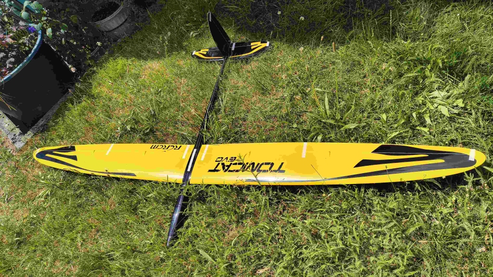
MY FIRST BROOM HANDLE!
the airplane has been on the market since 2012. After my Multiplex Flamingo Contest, I needed once again a pure F3B / F5B.
I ordered the attractive full CFG/CFK glider from Hepf in 2026 for €669.
Distributor: HEPFAirfoil: strictly secret. Hope it’s a good one!
In the navigation menu it continues
Imprint
Name: Mike Sandau
Contact: E‑mail: webmaster@lamasoft.tech
Do you call it “unboxing”? No. But maybe on the English page of this report :-)
Delivered quickly—it wasn’t much time for anticipation.
Pictures: from unboxing
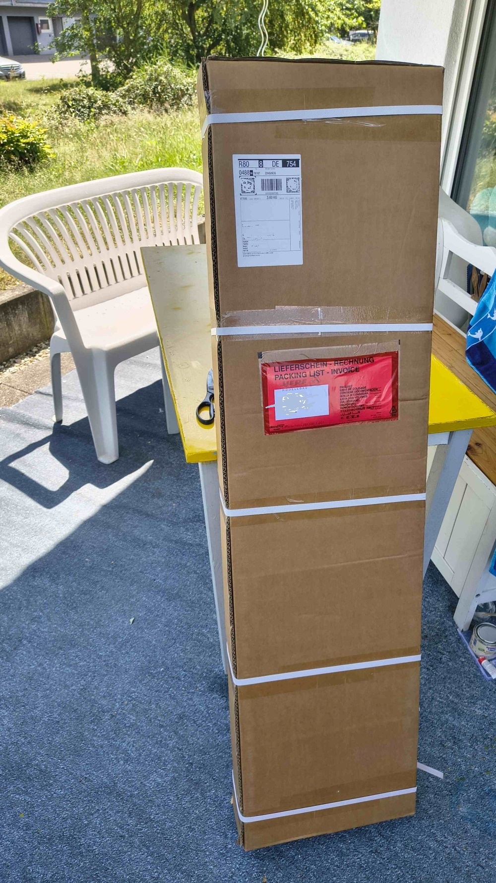
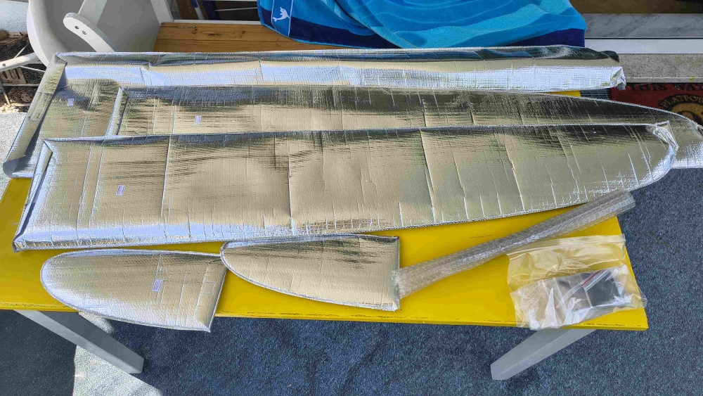
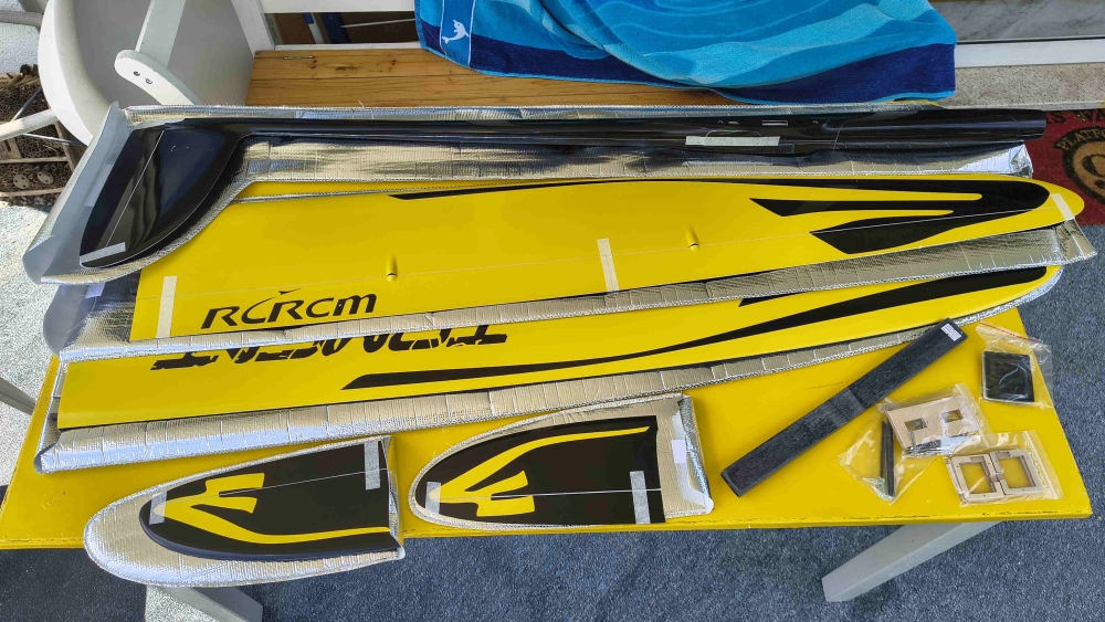
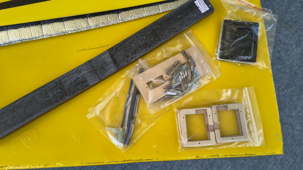
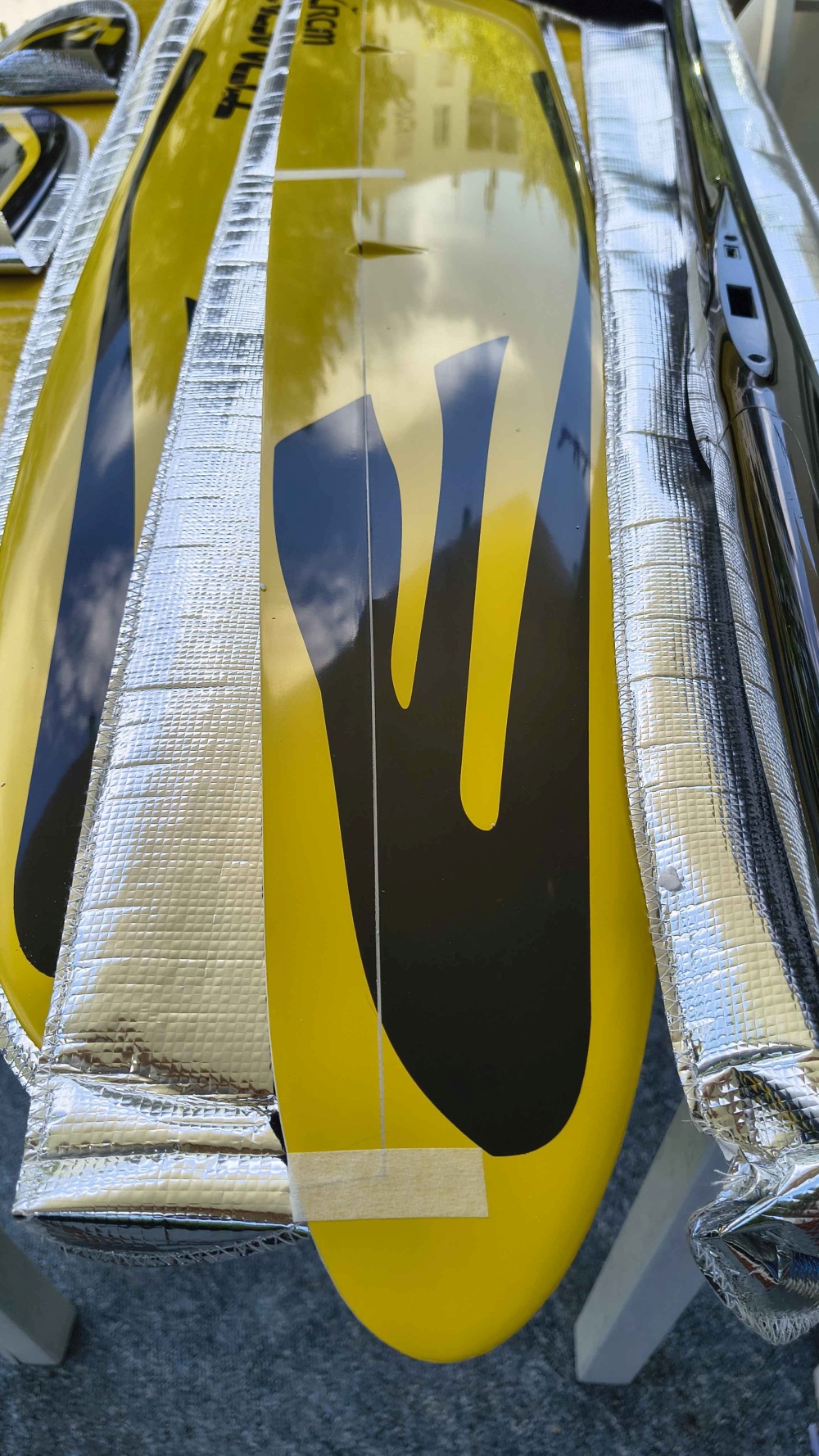
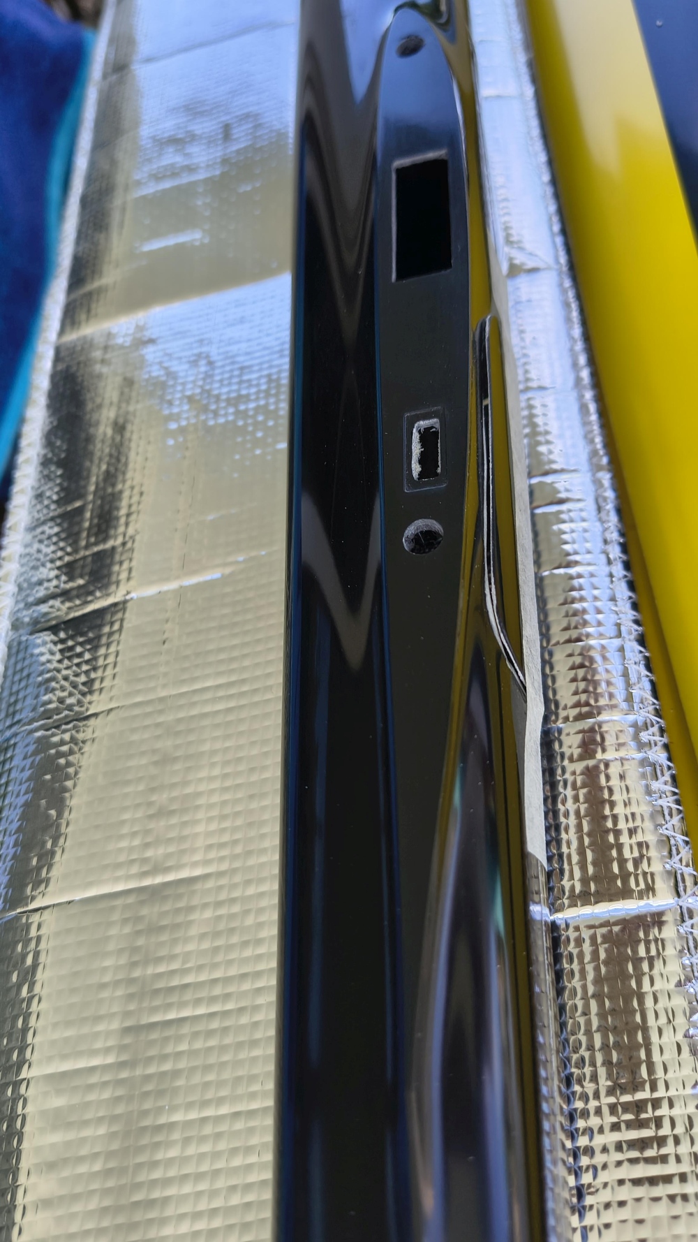
Make it yourself! 19.6.2026
Here you’re allowed to think it through yourself.
As it should be for a real F3B model: you may push it hard in windy weather.
A feature I first got to know with my 1983 Simprop Optima, and which I still use today for my old-school F3B. Only this year was I able to fly it at 4–5 Beaufort thanks to that.
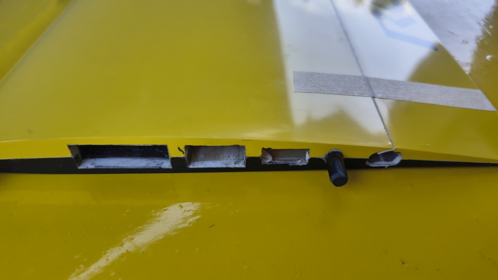
Here is the middle compartment for ballast!
In other build reports, a rod was assembled from individual plates. The best thing I could find for that at the hardware store was:
a 20 mm × 4 mm steel profile, 1 meter for €4. So first cut it up—that part was still okay.
I managed to get out; together it yields 20 mm × 8 mm. Undersizing is mandatory here. The two rods are held together with double-sided adhesive tape.
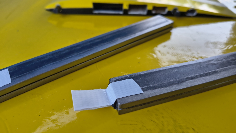
Getting the 20 mm to the undersize then required 1 hour of reworking with an angle grinder.
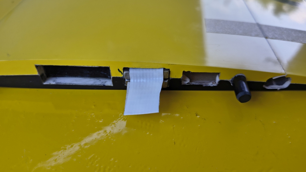
...Tadaa. At some point it then fit. It must never get stuck, otherwise: BIG PROBLEM!
m1Ballast = 420 g
I can still pack that in to increase wing loading. Compared to my Simprop Optima with a 2.7 m wingspan and 500 g ballast, it should become very similar.
Practically, you could separate the two parts fixed with double-sided tape again and use them individually; then the weight would be:
m2Ballast = 210 g
Wings are meant to fly 20.6.26
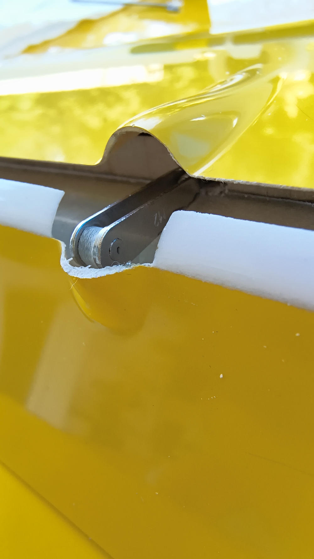
It’s a 4-flap glider, and the linkage of the control surfaces is nicely done—designed to be low drag. It should simply look elegant. I wouldn’t risk my life by stepping into an aircraft like this.
Sturdy is another story. But I decided to take the risk and follow the suggestion partly.
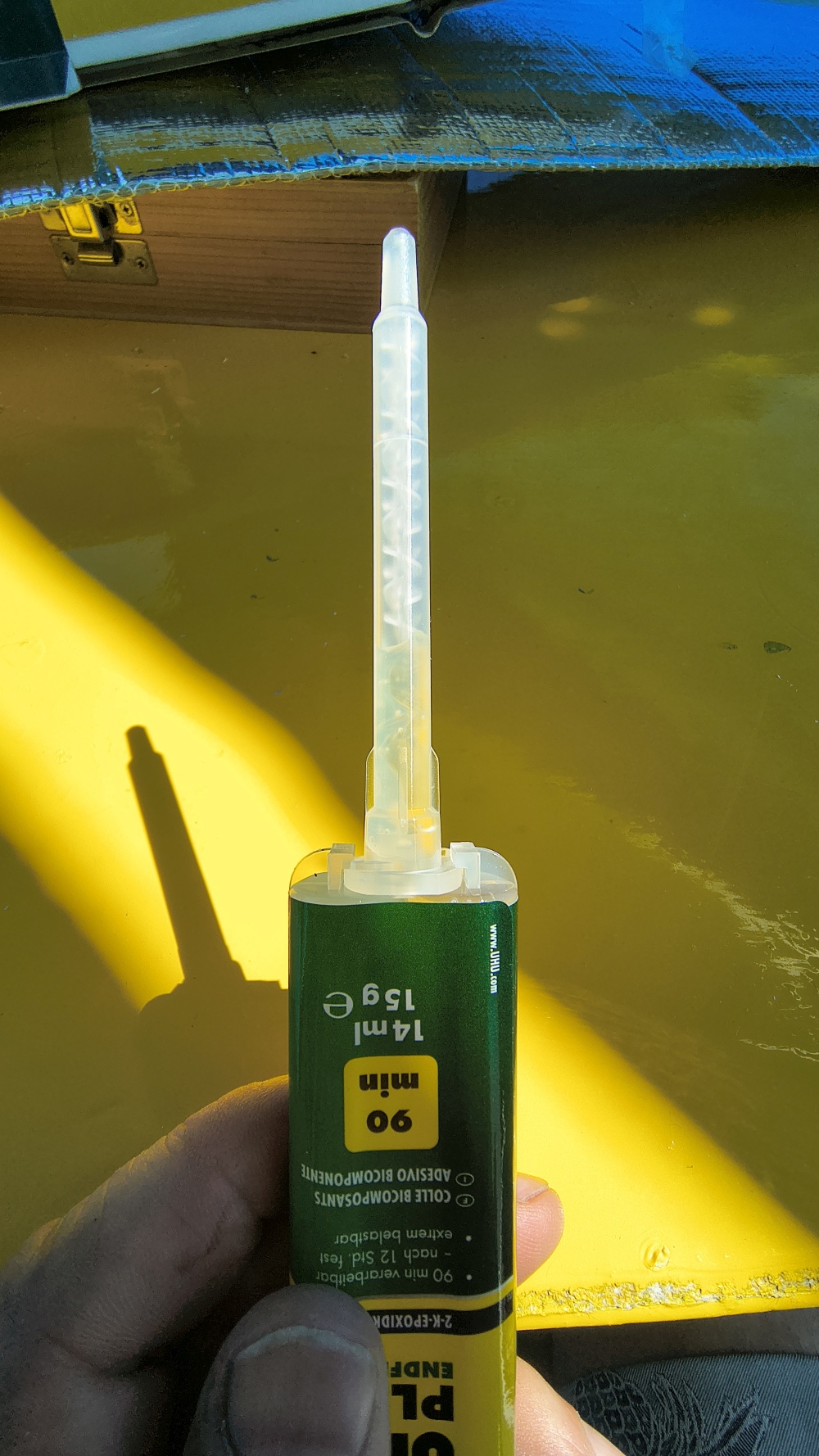
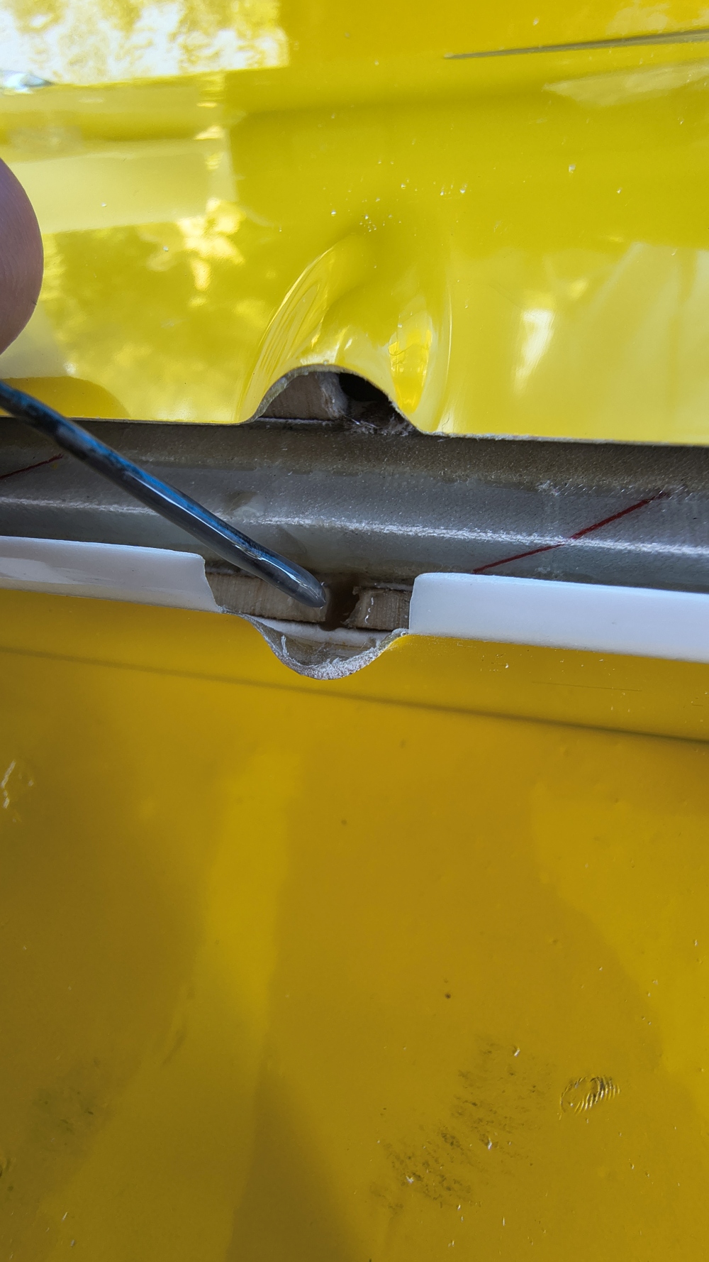
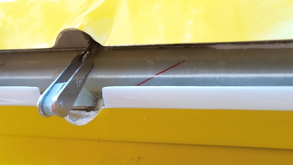
Points of criticism: the control horn sockets were epoxied; that usually comes loose again after a few years when the resin softens. No costs spared and the newest purchased—UHU Endfest in the pro version.
Endfest resin is available for €10 as a syringe—great for dispensing. But of course there’s a lot of waste. Use with the mixing tip is limited to two times. Then you have to buy a new package.
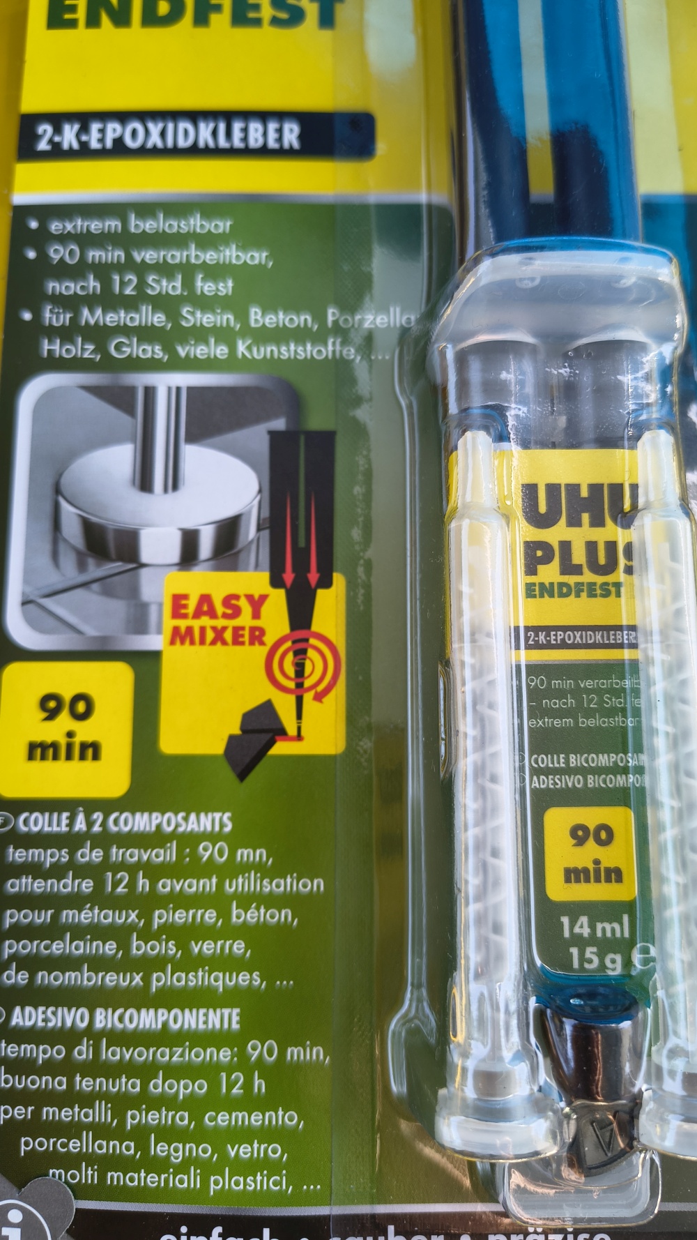
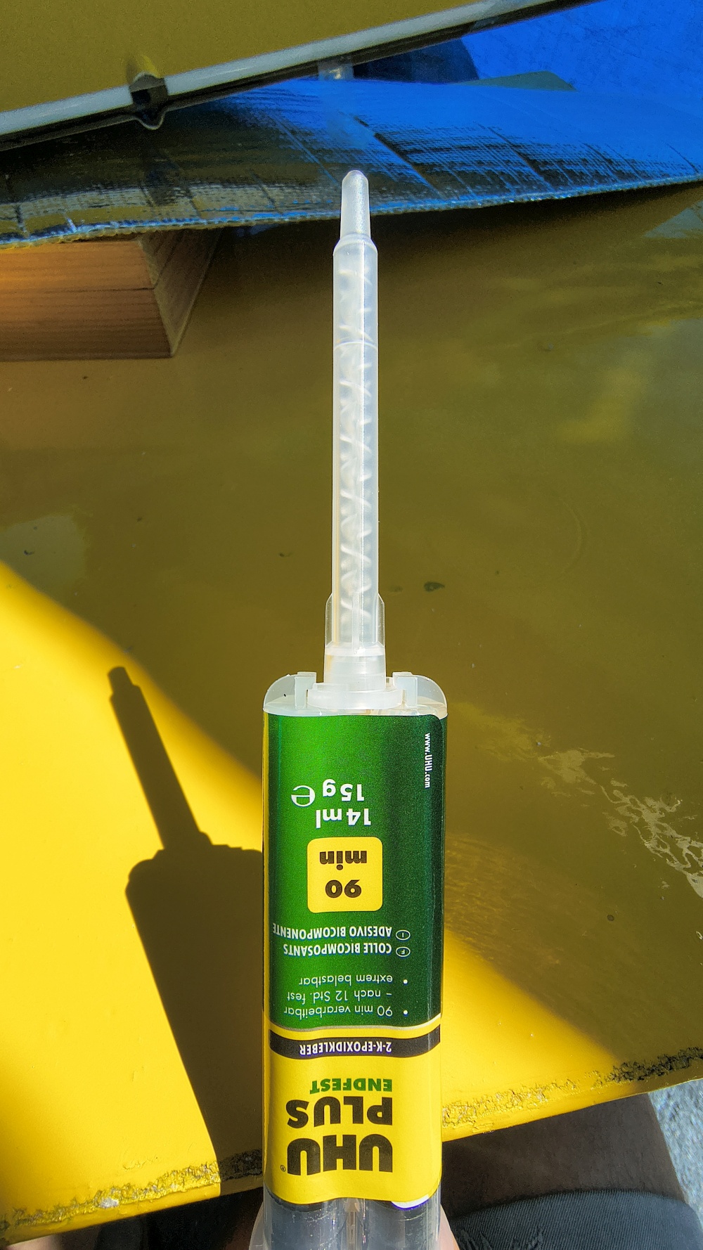
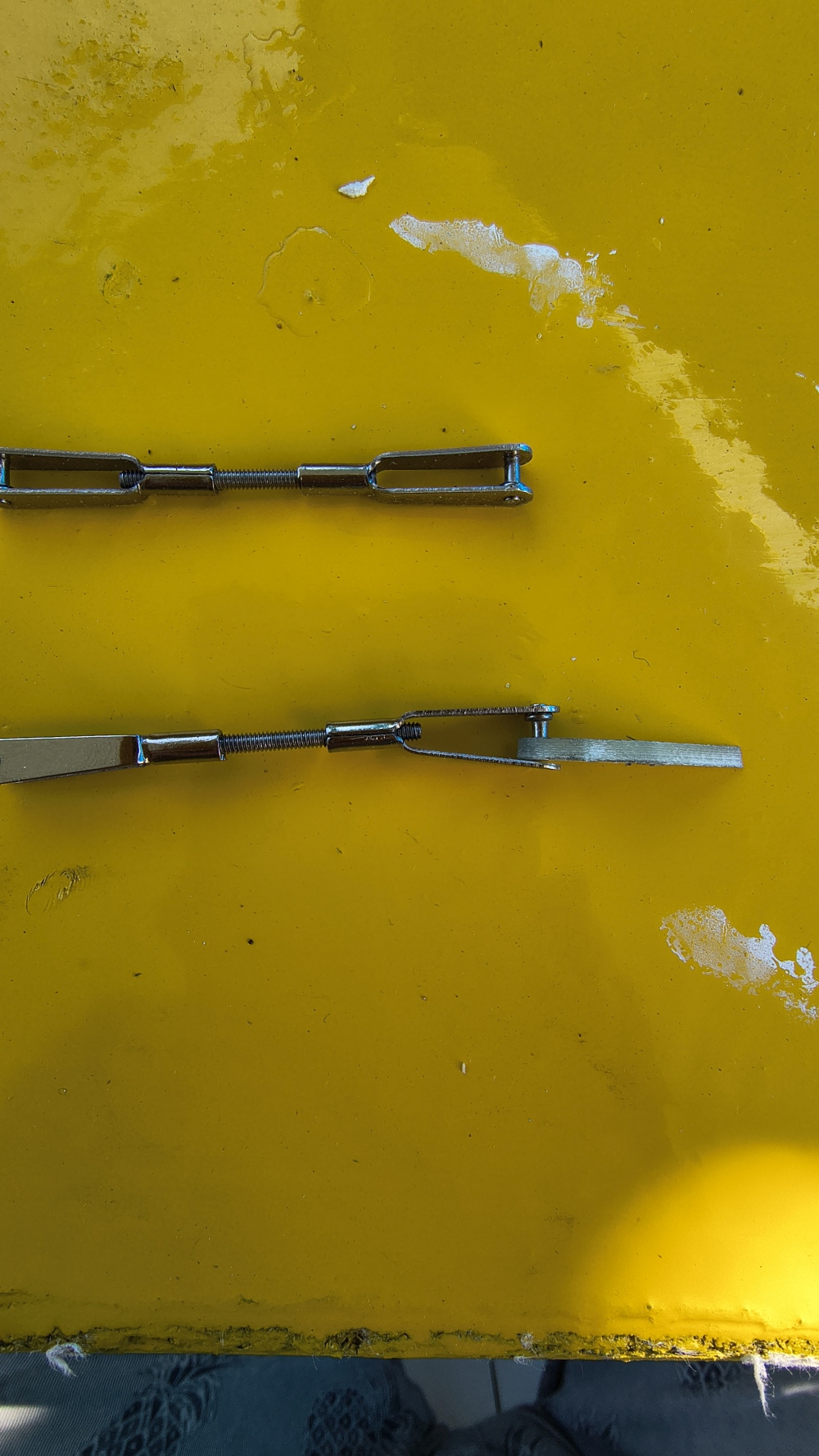
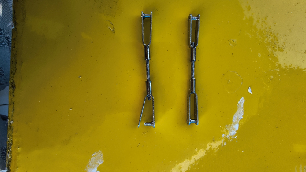
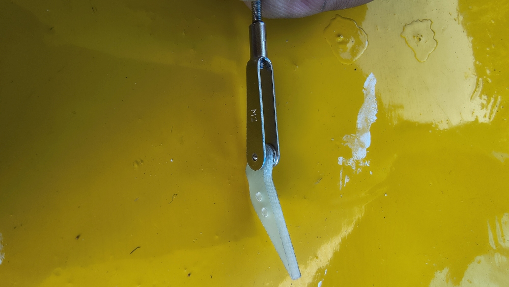
More criticism of the supplied clevis heads: In only a few kits have I seen acceptable quality there in recent years—quality like I knew from the 1980s from GRAUPNER.
As you can see here, the heads already bend when you try to fit them normally onto the control horn. They stay bent. RISK. Quality is still available at MULTIPLEX ; I bought the heads there—they’re the good ones.
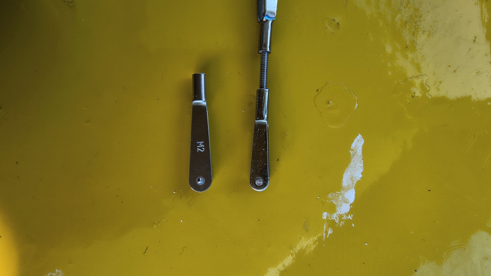
Enough complaining—let’s get to the installation. Preparation
- roughen everything up
- check for freedom of movement on the control rod thread before applying glue
- epoxy carefully. With Endfest you can take your time
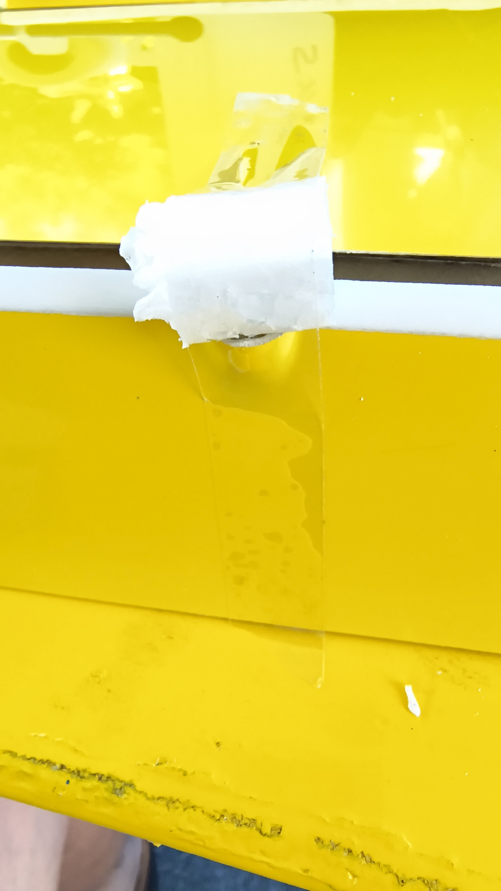
- fix everything with TESA
- solder the cables, plug-in system
- wing panel locking / attachment
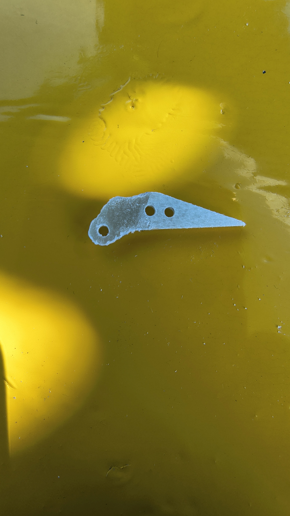
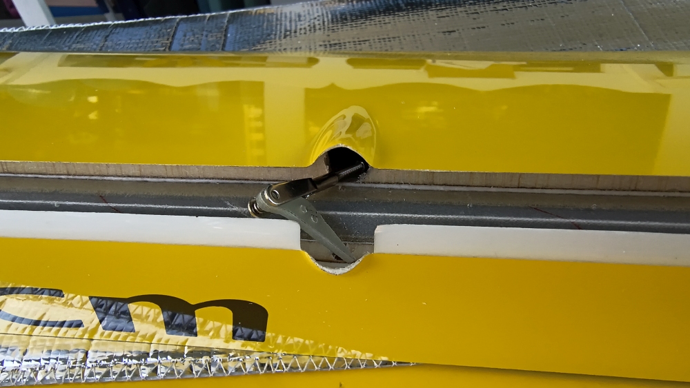
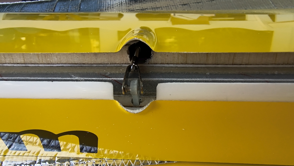
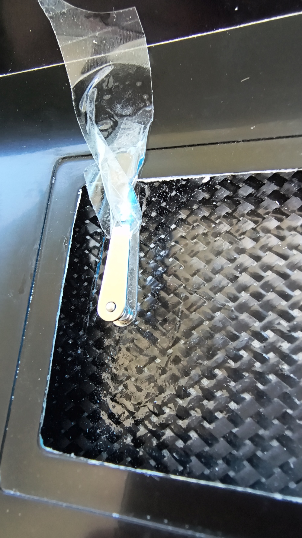
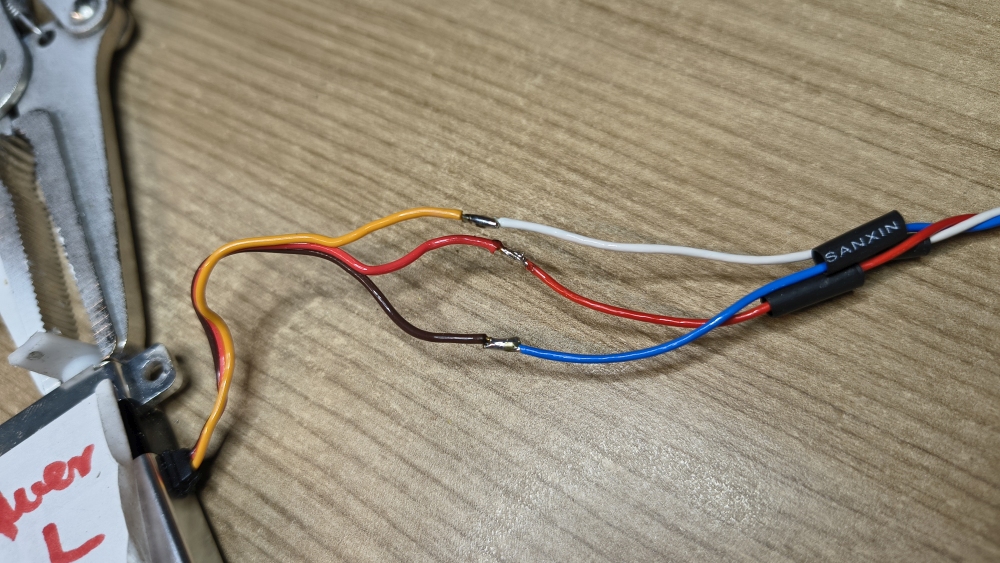
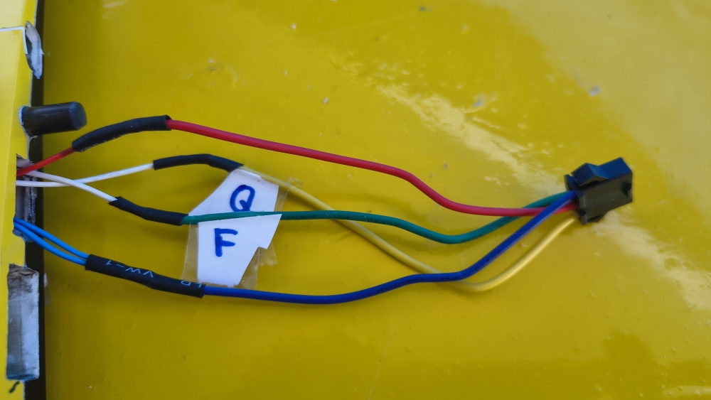
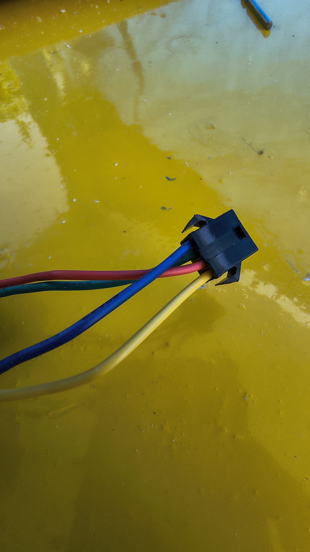 / I only use connectors with strain relief now.
I rely on the classic TESA film. It has never disappointed me as long as you use a new piece of adhesive tape
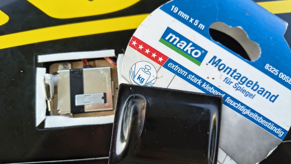
Cover closed: the two wing panels are finished
You can manage it in a day if everything goes smoothly. And if you don’t have to consider collective bargaining / union agreements :-)
Safety First
Not cool, cumbersome, and impractical. This is the kind of technology you need to rely on 100%. Our hobby knows no compromises.
Every weakness reveals itself one day in a cruel manner.
Here are my favorite connectors—I'm not a fan of permanently glued connectors without strain relief. Just 2mm slip and the model is done for.
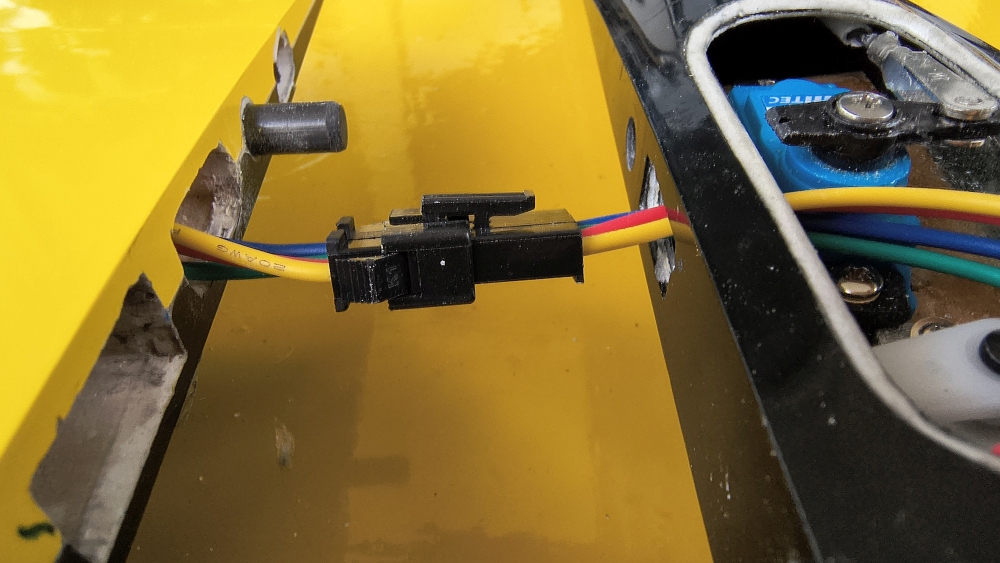
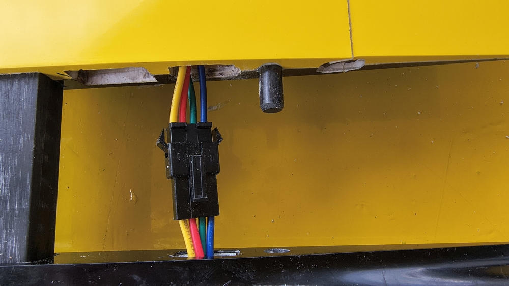
No, no...
Source: Mükra Electronics Shop
how to do this ?
what are my possibilities
three pictures show possible arrangements
Center of gravity is taken care of for all three
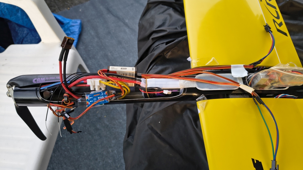
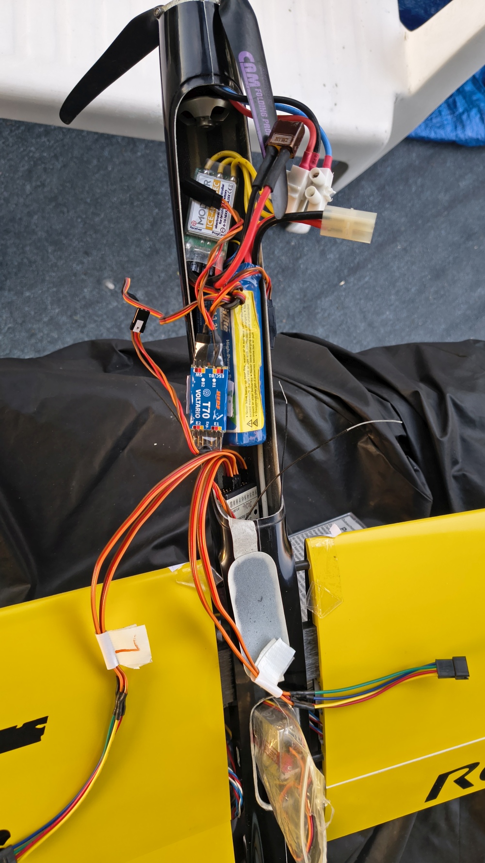
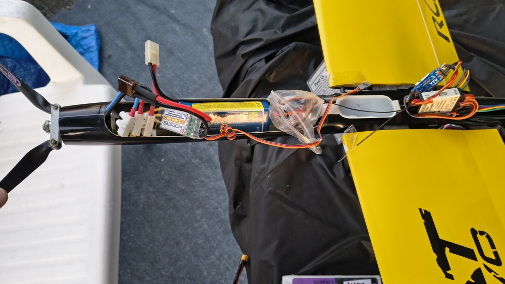
After finishing the wing, I thought I’d quickly install the servos into the fuselage as well, and then the model would be almost finished—yeah, right!
Installing the servos in the narrow fuselage is one thing, but there are also numerous restrictions regarding the servo placement: you have very, very little choice, due to
- additional cable routing
- the wing connectors
- the servos must not interfere with each other
- also, the length of the servos and the height of the servos are critical
- they must be positioned in the middle.
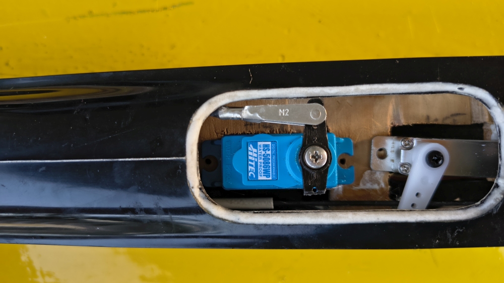
What also came into play is that the fuselage has far too small an opening for the servo compartment for you to screw the servos in. That’s why I decided to drill a hole in the fuselage so the servo can be fastened through the hole to the servo mount board.
In total, I spent three hours thinking it through—figuring out how to make it fit best—and I carried out numerous test-fitting attempts with cardboard and double-sided tape until I finally came up with the final shape of the servo mount board for my servos and the model.
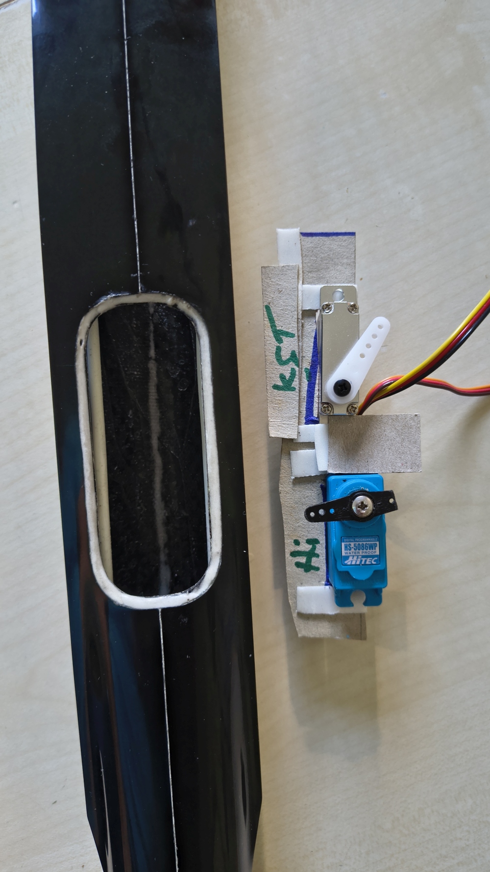
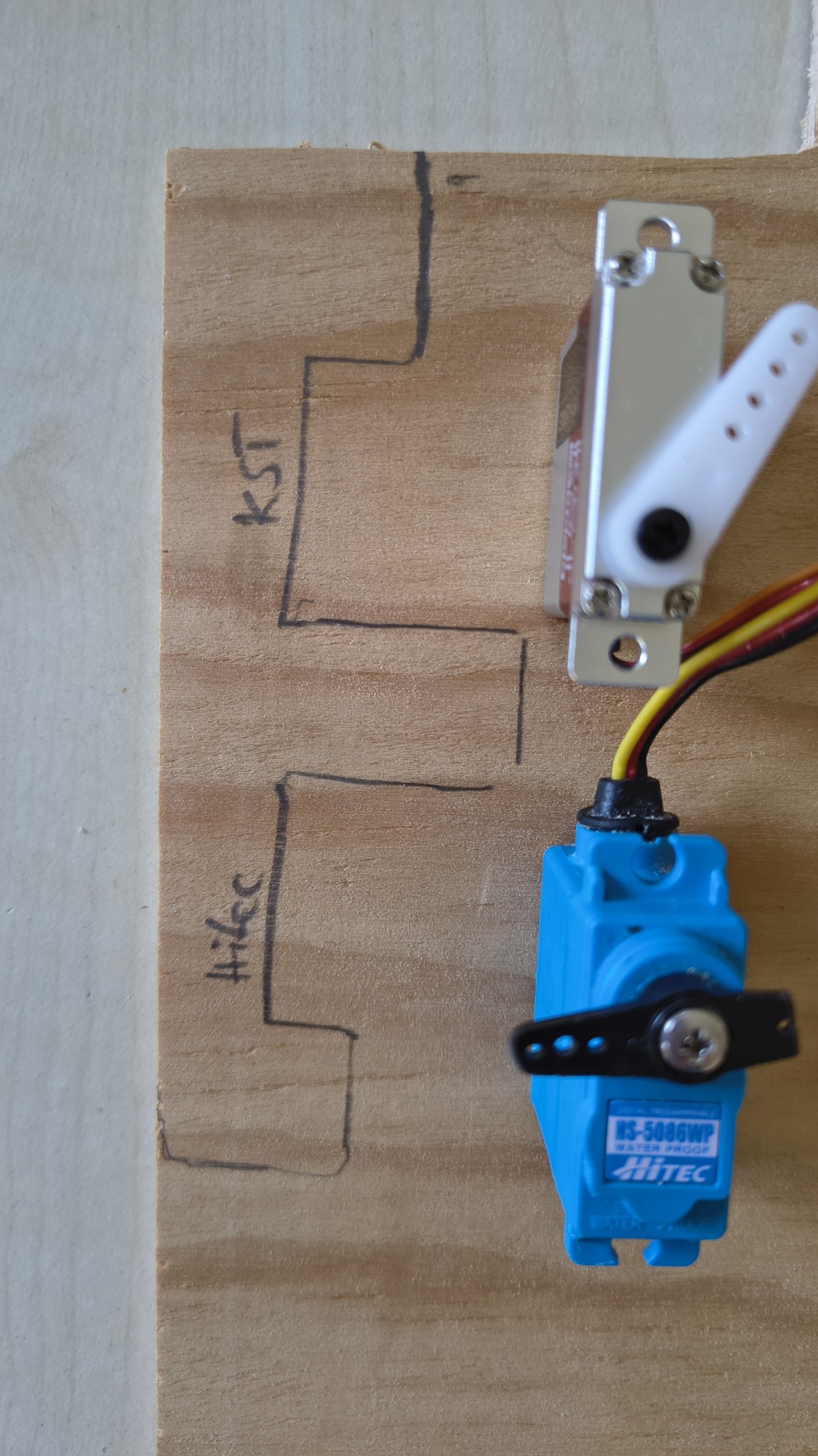
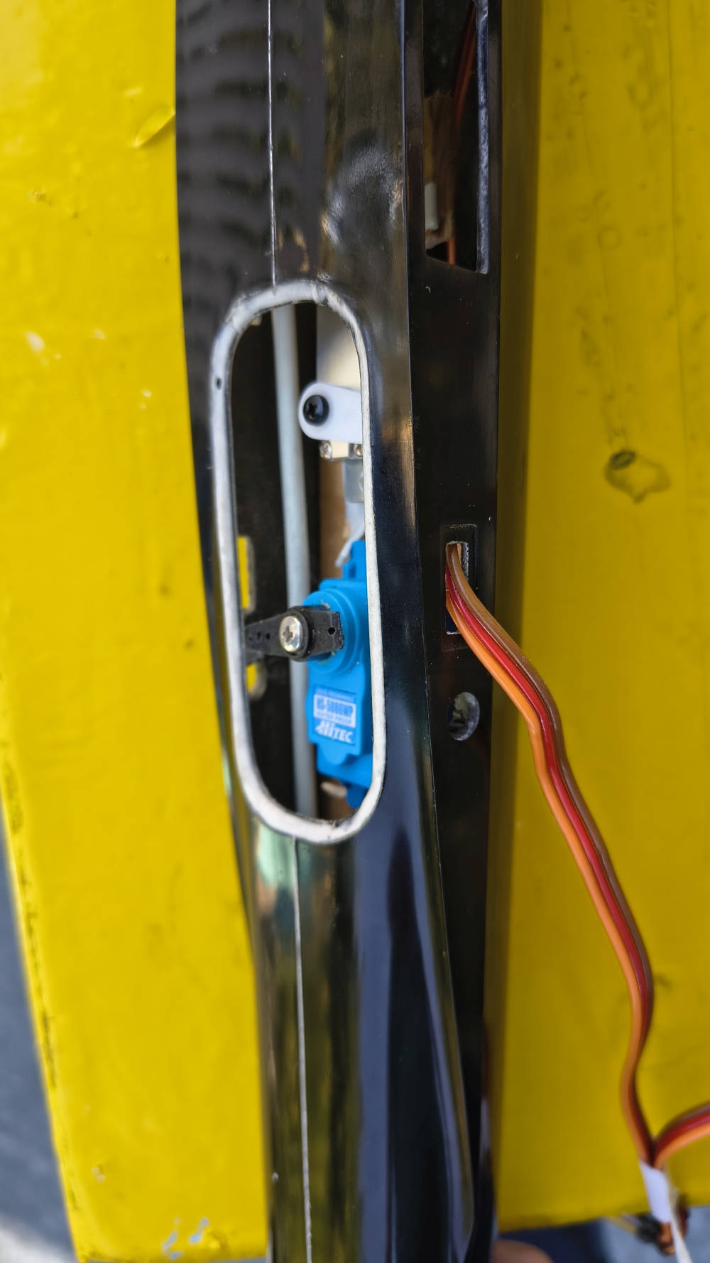
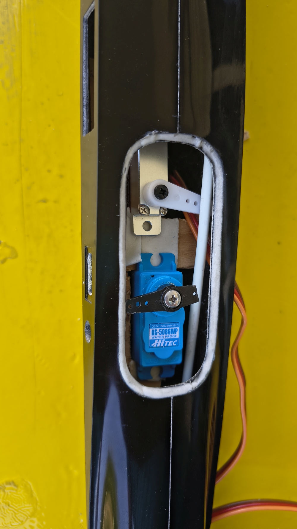
Fitting the appropriate servo mount board with the servos in place was then no big deal. But connecting the linkage for the rudder was also very difficult, because here too essentially everything is predetermined how it must be done. So there were very few options.
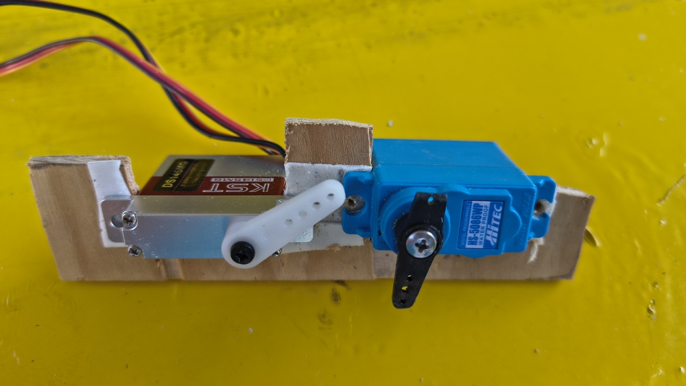
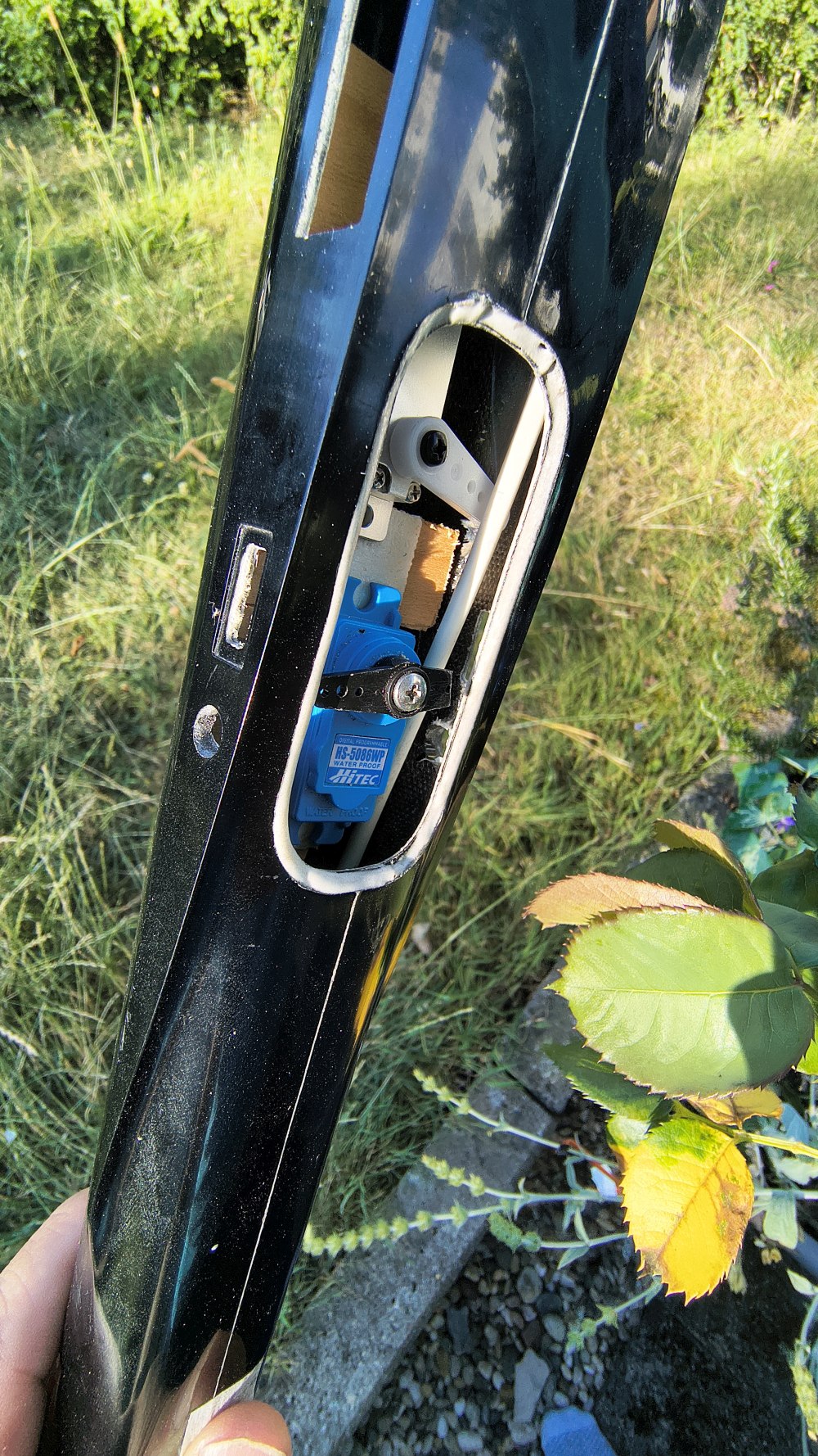
However, I didn’t want to use the supplied, glued-on horn. I prefer screwed-on horns where possible—more stable and more reliable. And here too, you can see in the pictures how tight the opening for the clevis is and how little space there is between the clevis and the horn. During installation, there is no space even down to a tenth of a millimeter.
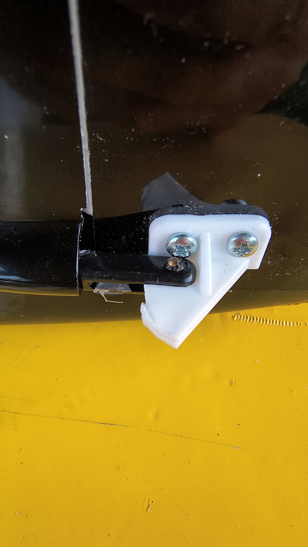
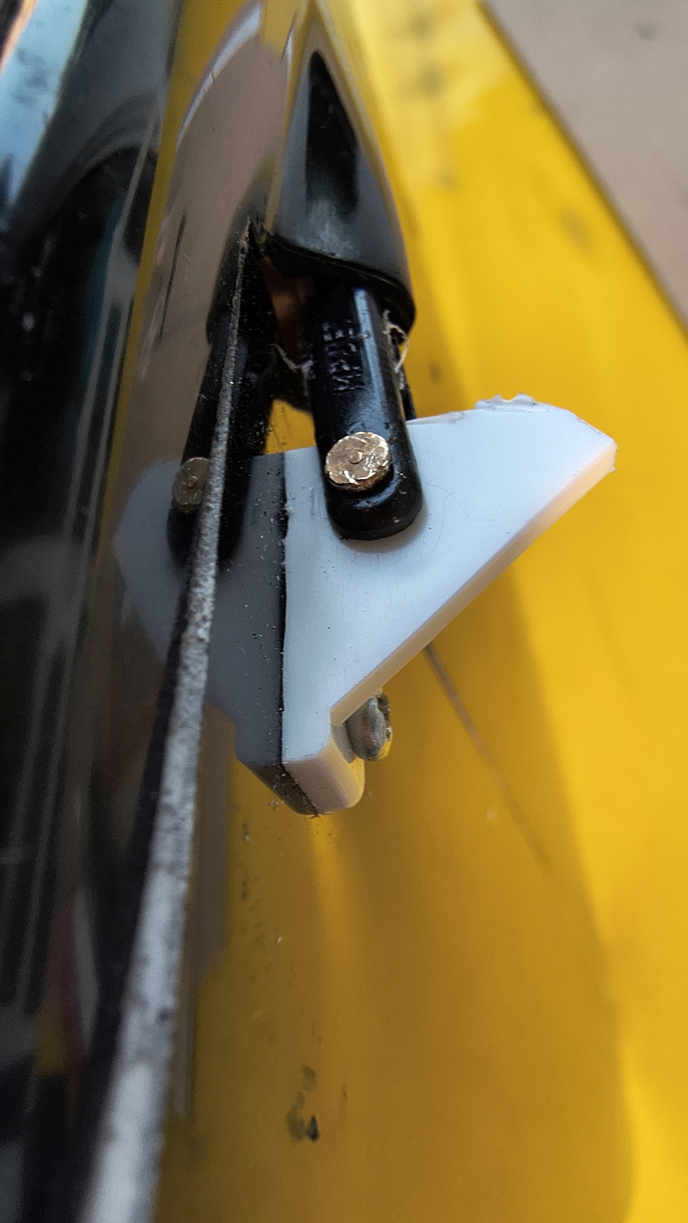
Everything then moves sufficiently well, but you don’t reach the much larger deflections—about 20 degrees to each side—that the model specifies.
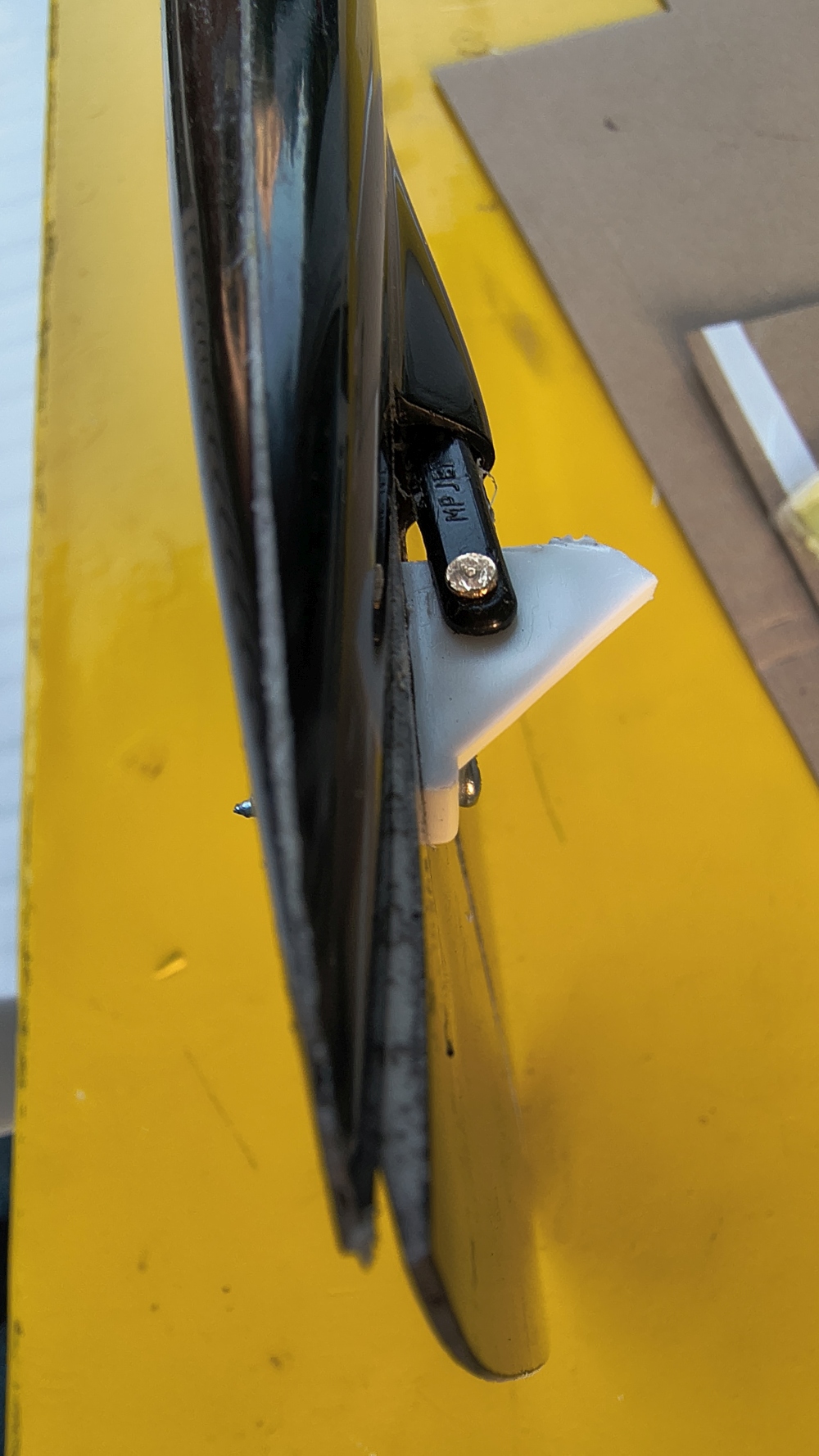
To get the clevises onto the carbon-fiber (CFK) pushrod, I tried a recommendation from a very good professional model builder: attaching the clevises using hot glue, since for the metal clevis sleeves there actually wasn’t really any space—there wasn’t even space for one.
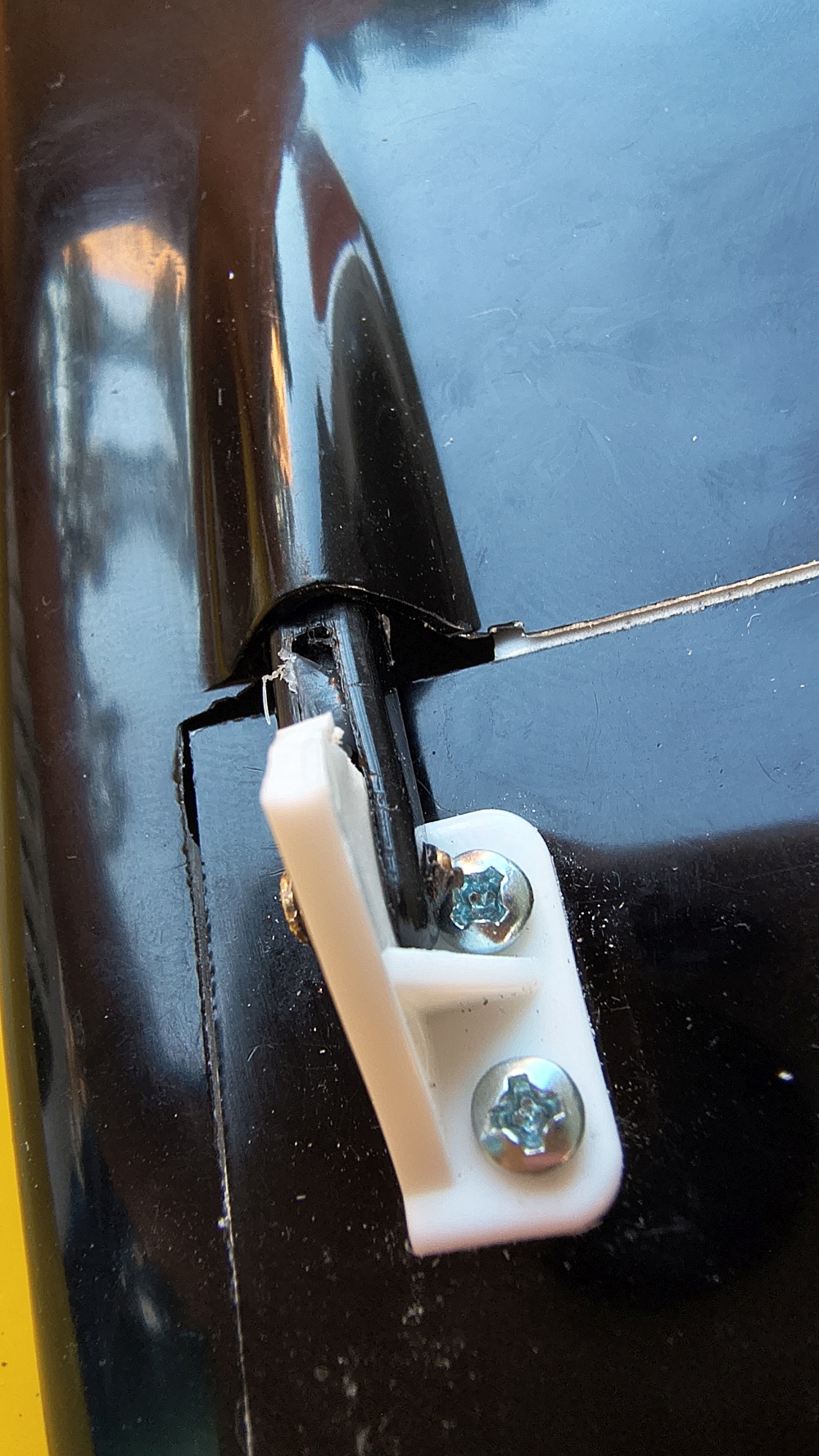
With hot glue, you can then also change the position afterward (by heating it again to over 80 degrees and shifting the clevis on the CFK pushrod if necessary). However, everything fit perfectly on the first try, so installation was finished after about 45 minutes.
That was absolutely no fun, but the hardest part is over now!!! Hallelujah!!!
Propeller selection, test stand, performance — 26.6.2026
Drive/propulsion data:
- Controller: Modster ICE 40 A
- Motor: e-Flite Power 25 — 870Kv — max: 32A, 44A (short duration)
- Battery: 3S with either 2200 or 3200 mAh; either should work
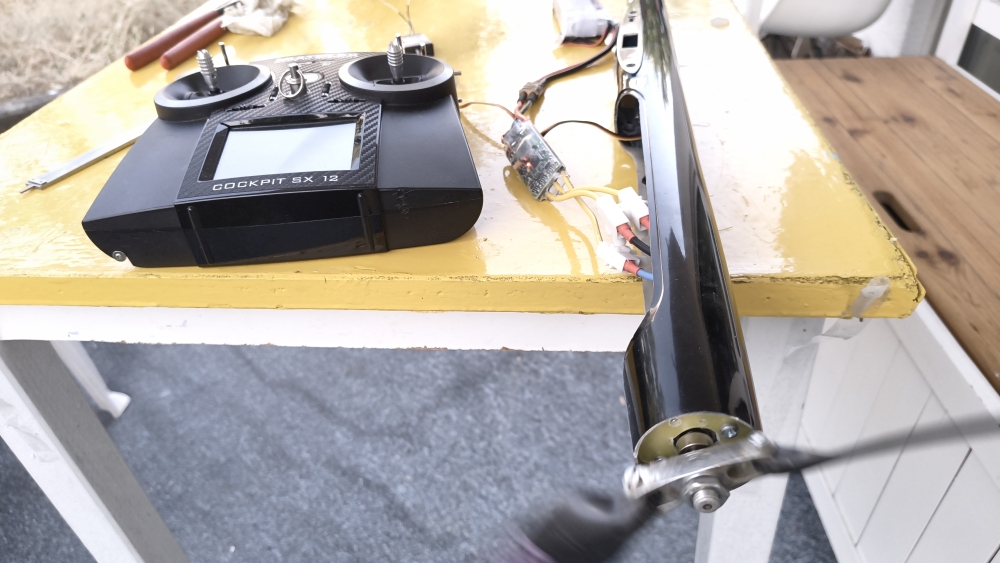
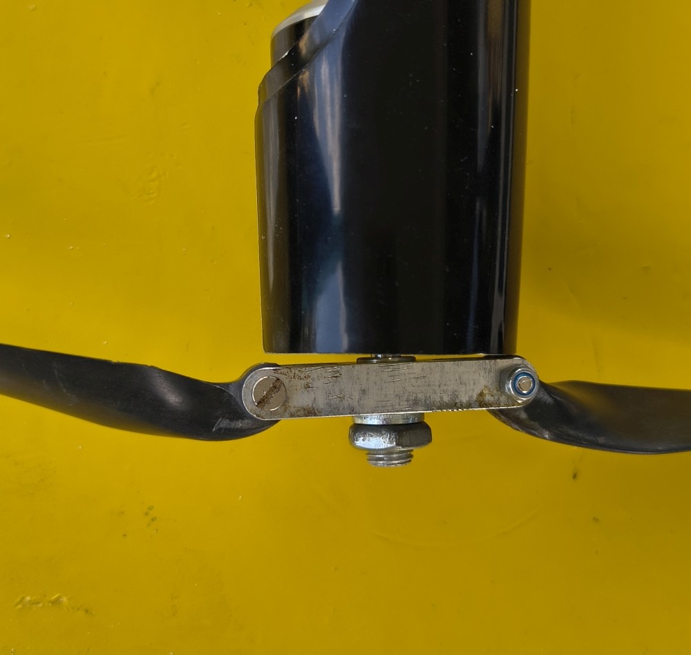
Here is my motor test stand.
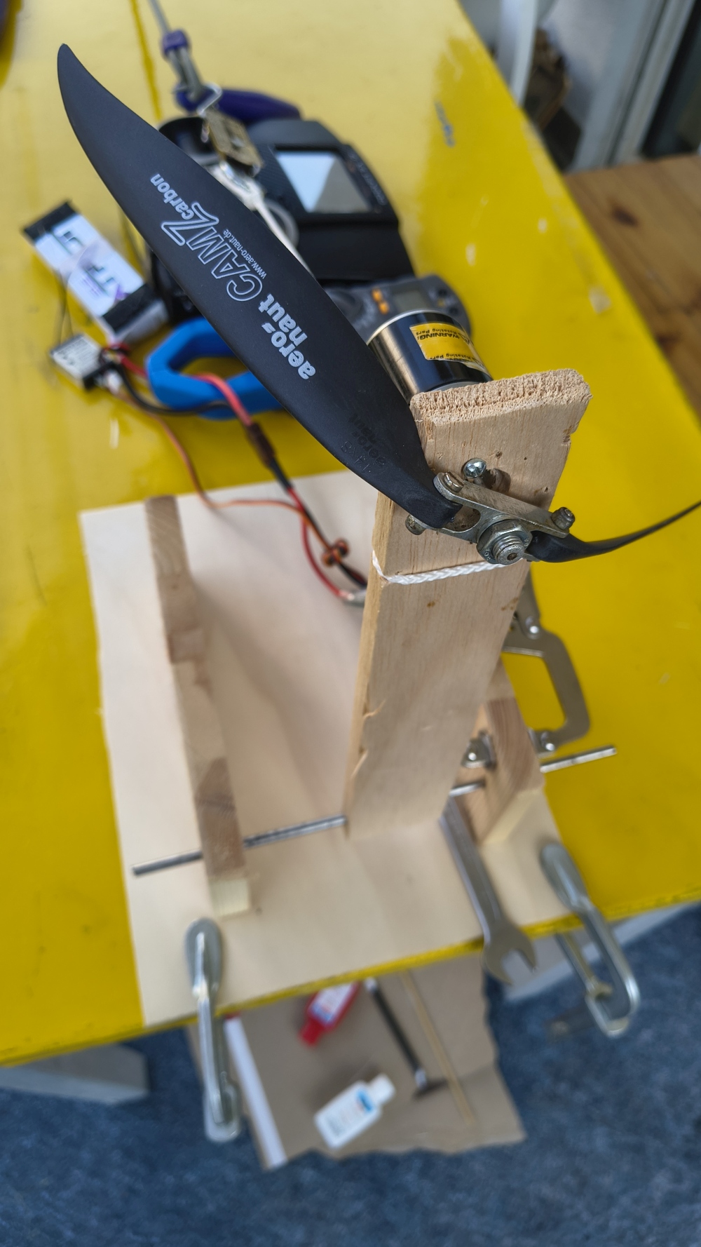
A test video with a 14 x 8 propeller.
And another one with a 12 x 6 propeller.
Clear winner is the reasonableness of modesty:
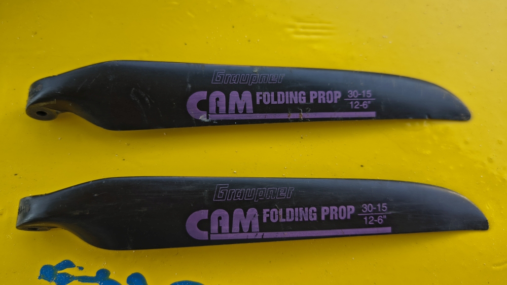
The smaller propeller produces 2.1 kg of thrust; the model weighs a bit more than 2 kg—so even with the small propeller we already get a good “vertical speed”.
Motor Mount Tension 28.6.2026
It was meant kindly by the manufacturer, but I can’t do anything with it. 1. You could bore it out, but because of the slots for the
nuts, it would then become unstable. Since I make so few compromises, the motor mount tension goes from RCRCM into the drawer
to end up in the trash one day.
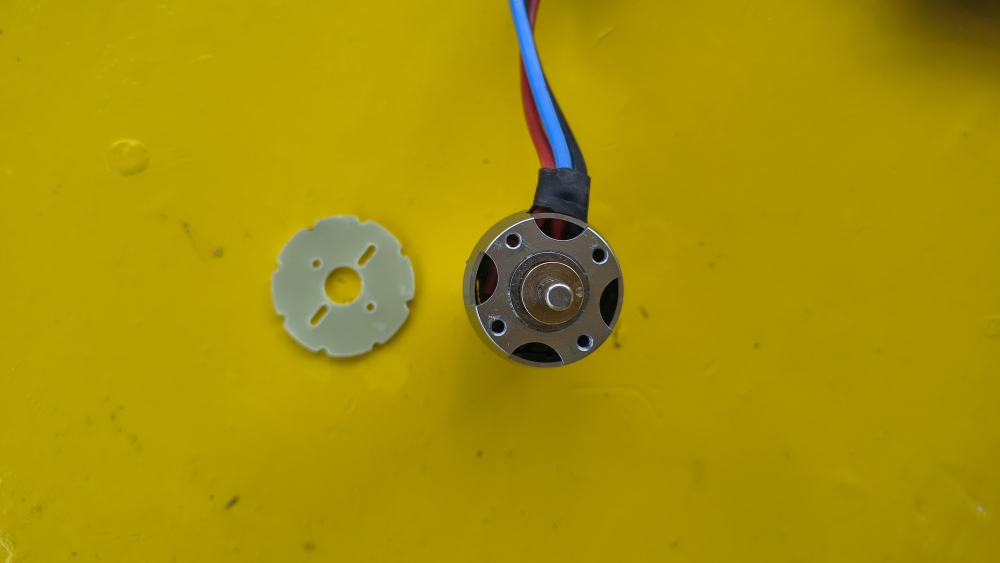
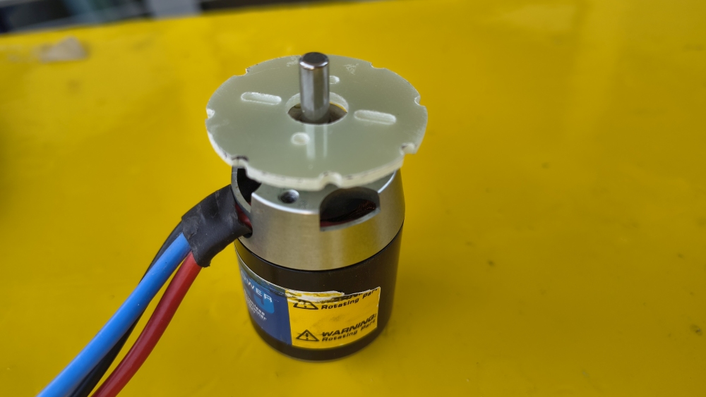
The measurements are transferred to a template and fixed in place with quick-setting epoxy.
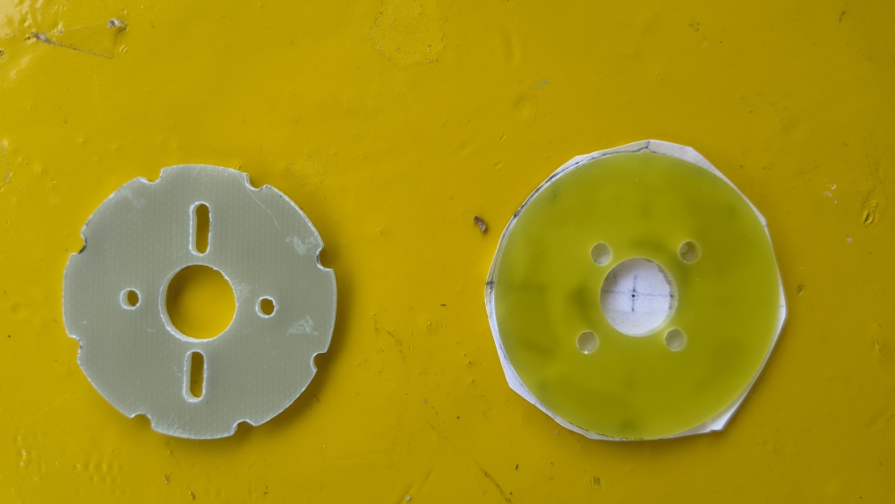
In wise foresight, I ordered another one.
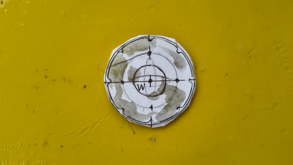
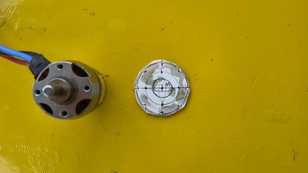
to fit/adjust
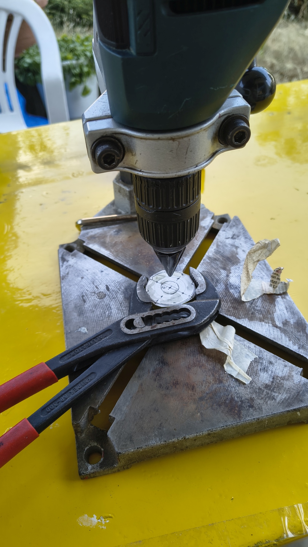
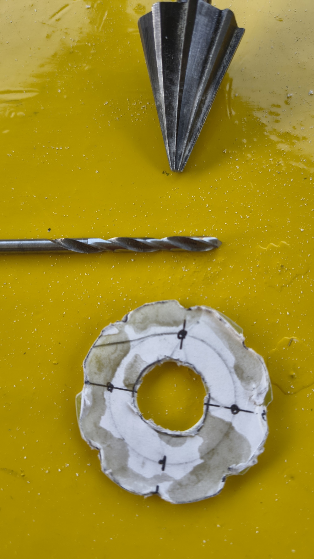
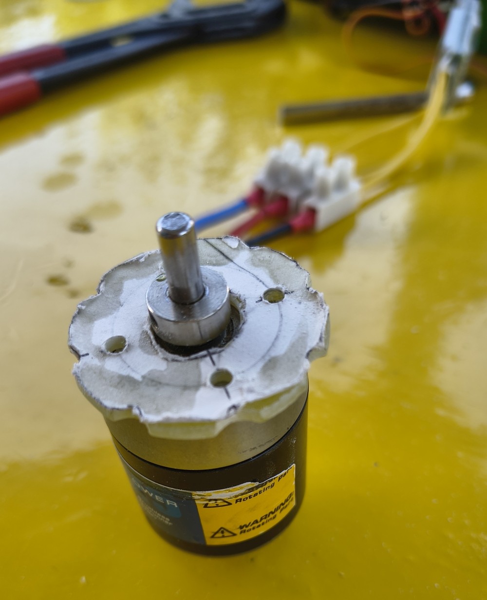
now it fits.
Test installation, trial run 28.6.2026
I simply slid it in—I’m slowly starting to dare to run the motor to find out whether anything rubs.
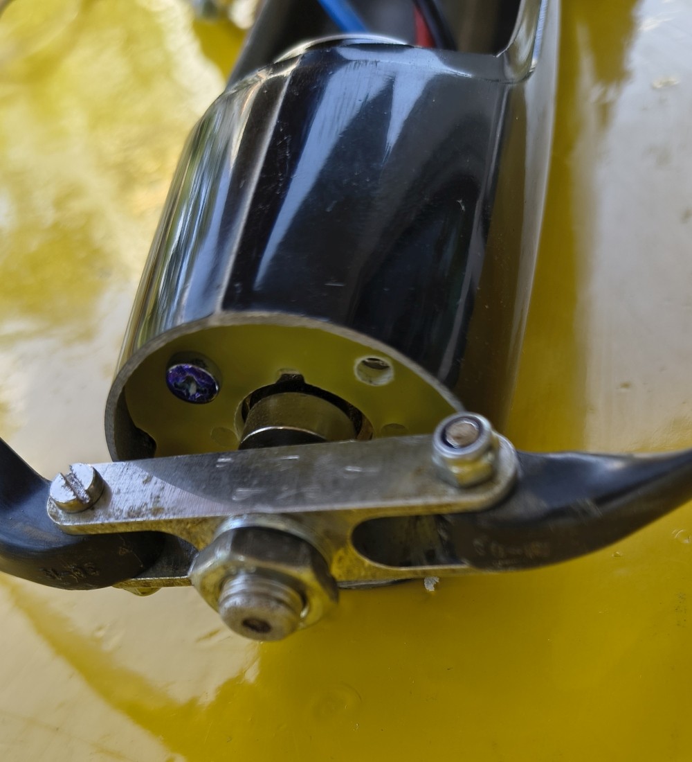
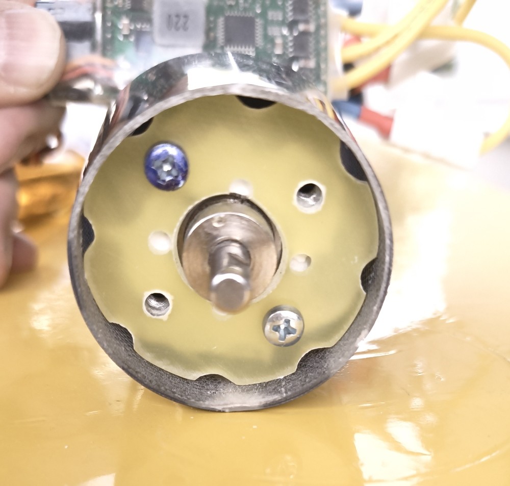
but everything is OK. Carefully take it out again. Fix it with 2–3 drops of quick-setting epoxy so that nothing moves while curing.
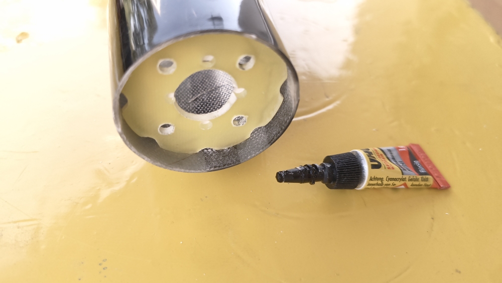
Mike’s brilliant trimming method 28.6.2026
Who invented it? Mike.
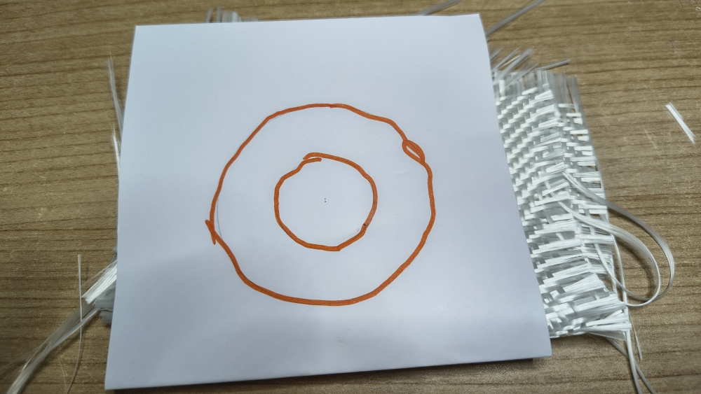
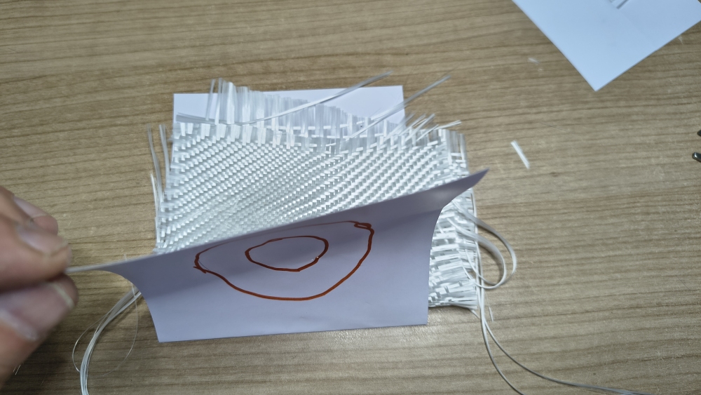
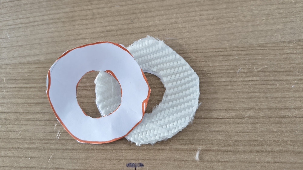
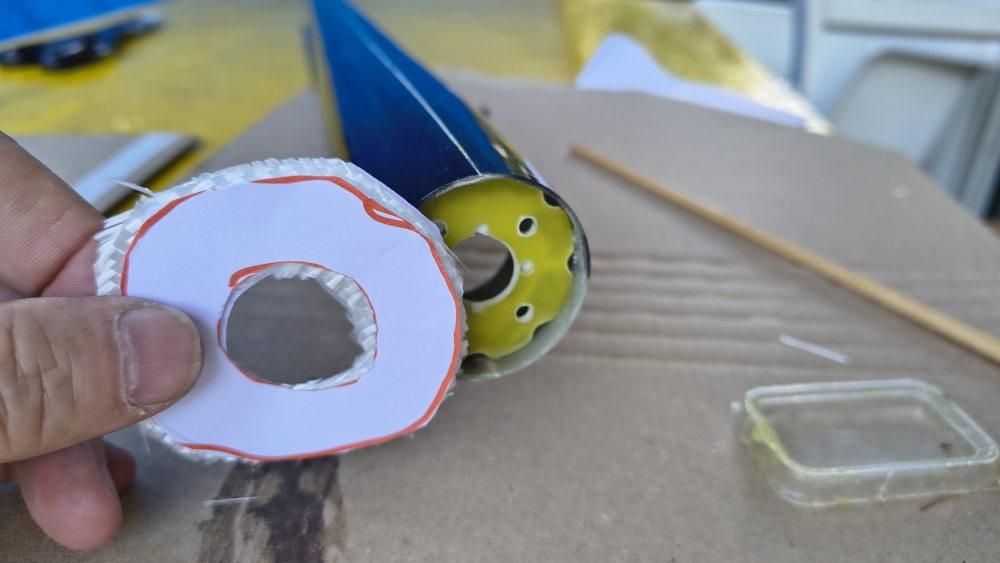
Liked my YouTube(TM) video—or don’t bother.
Video: Mike’s brilliant trimming methodAir conditioning 28.6.2026
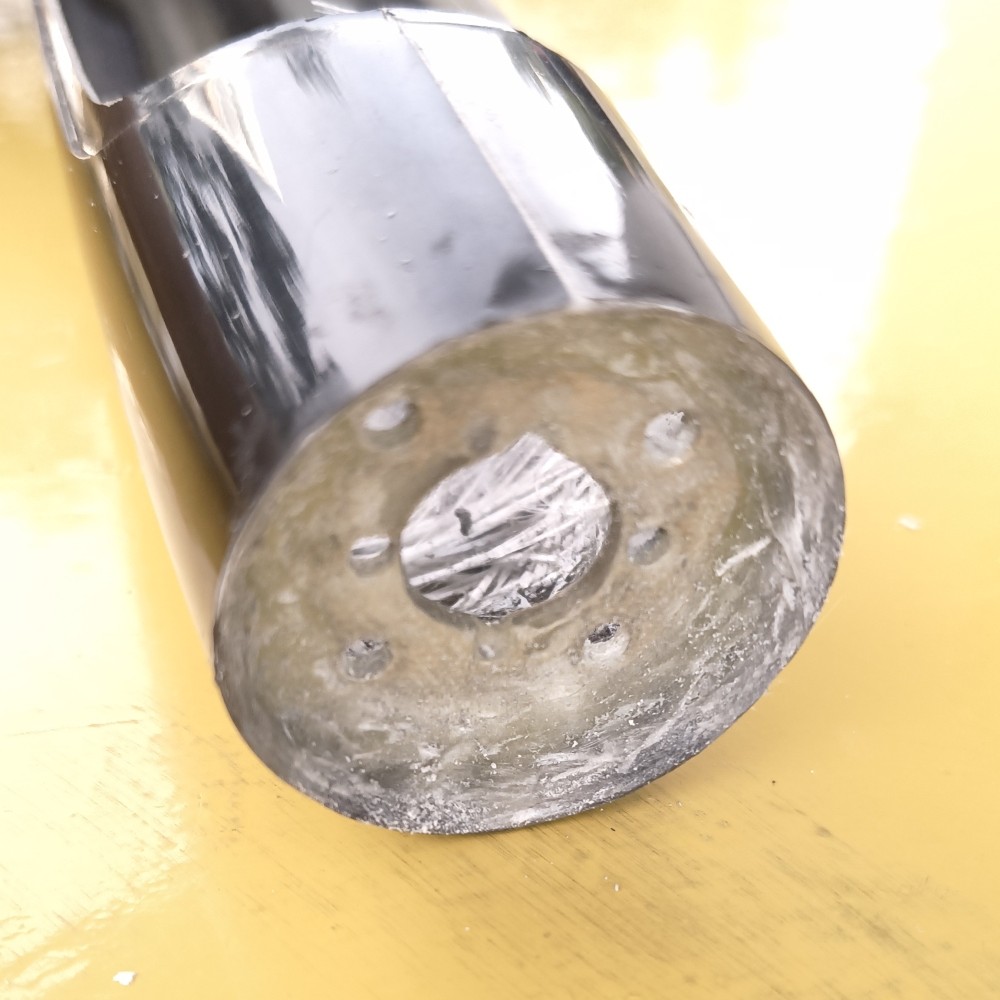
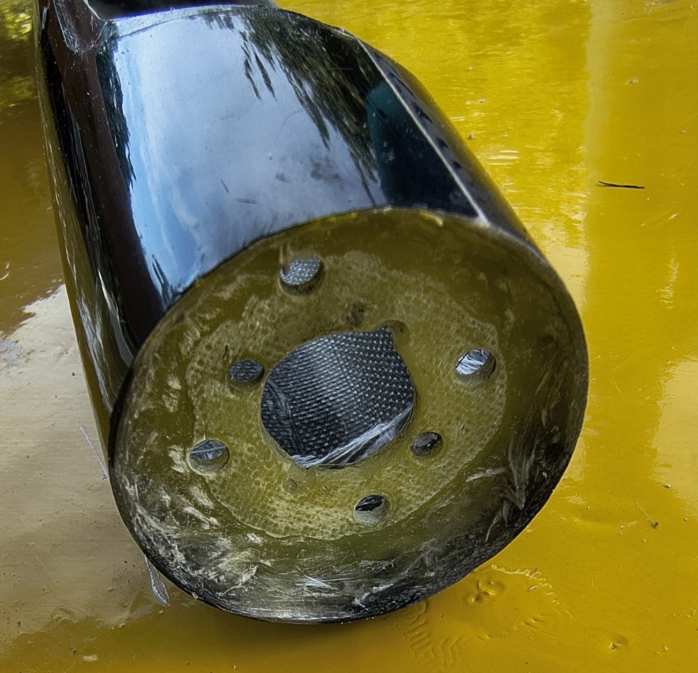
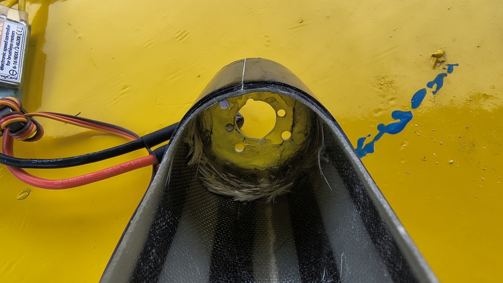
The first test on a 33°C warm day already had the engine hood radiating a fair amount of heat. I’m afraid of high temperatures.
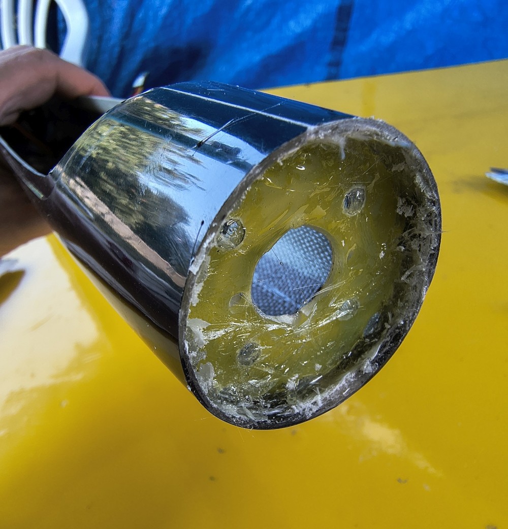
Next, a temperature sensor will be added to the model so I’ll know!
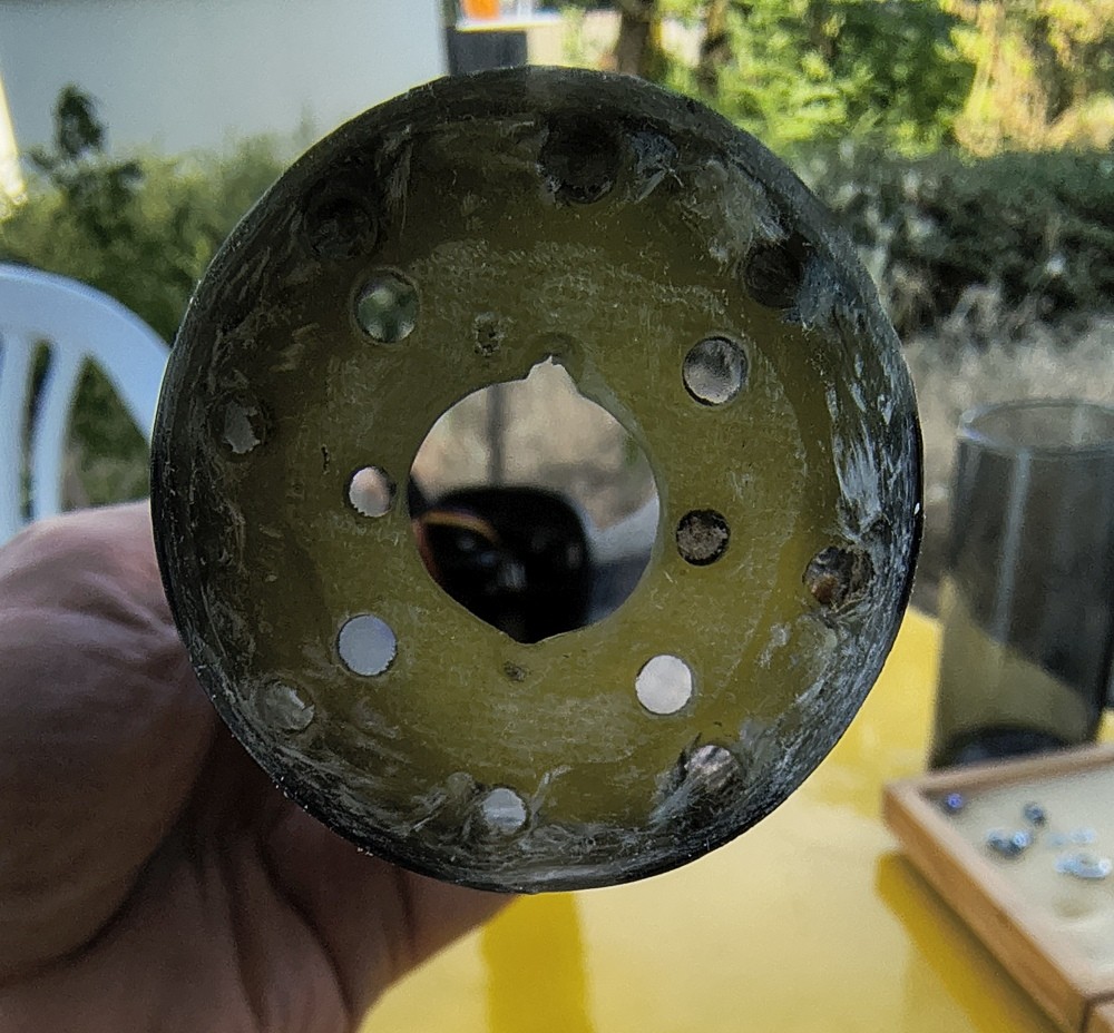
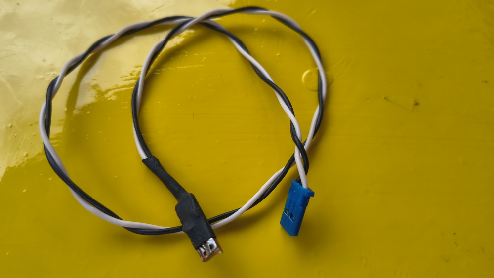
Temperature sensor 29.6.2026
You can easily make one yourself: Multiplex sells them, or you can get one at an electronics shop. It’s a standard PTC: PT 1000.
Multiplex doesn’t make any secret of it; I don’t think they earn any money from it. So just order it and put one into every model.
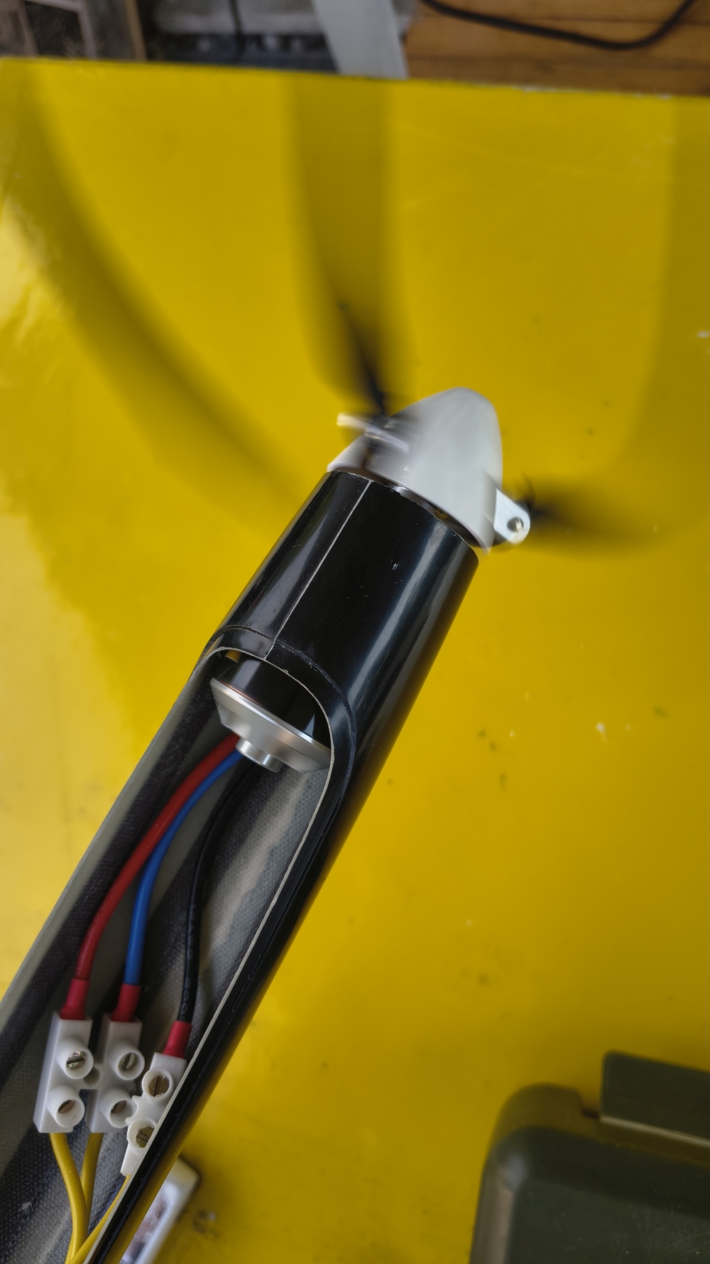
The most intelligent place to mount the sensor in the fuselage is directly at the three wires that go into the motor. There you have
the smallest delta temperature to the inside of the motor. But with this fuselage it’s too tight. Let’s see…
Spinner
It looks better, but until I know whether the motor gets enough cooling, I’ll fly without a spinner.
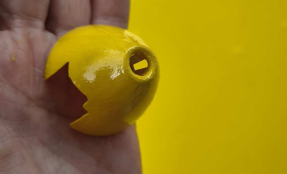
The spinner is from Aero-Naut, one of those clever “Cool-Nose” spinners. They have an air opening in the middle that further directs cooling air to the area of the air openings in the motor mount tension.
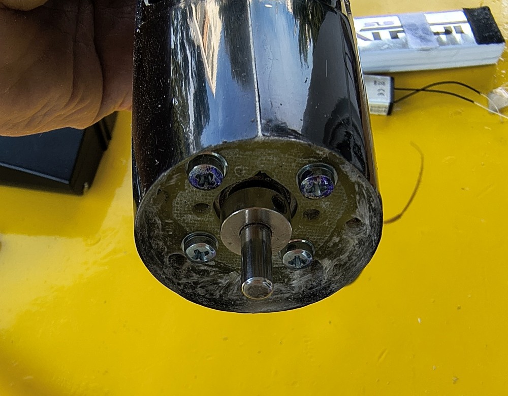
Does Everything Fit? 2.7.2026
This is the worst part of every model—it's the big moment, and nothing quite fits right—like a new pair of shoes, everything pinches here and there and needs to be adjusted.
A half millimeter is missing in one spot, something still needs to be fitted in another, the wing connector is pinching and needs a bit of filing...
But then, after an estimated 2 hours—which somehow became 4—you finally have the model fully trimmed and ready for launch.
With a small list of improvement ideas, but nothing that prevents takeoff. You can give the green light for the first flight with a clear conscience.
And you know: 1-2 years later, everything goes smoothly and effortlessly—no more tightness, like a well-worn pair of shoes: just assemble it, take it out, and UP!
I don't have many pictures of what the finished model looks like.
- Only the small 2200mAh battery fit, since I'm flying redundantly now
- Center of gravity very slightly nose-heavy—no unpleasant surprises there
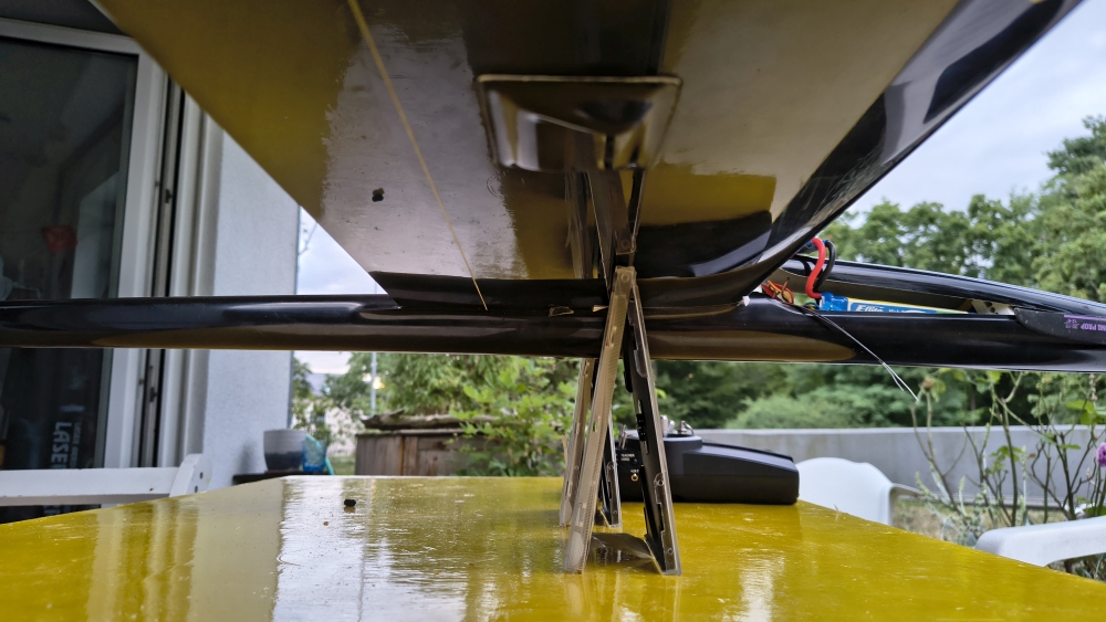
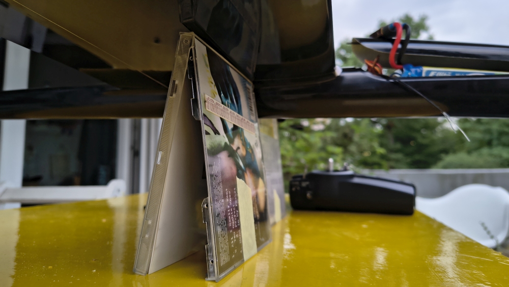
But there was one nasty surprise: the elevator servo collided with the wing connector inside the fuselage—something I'd actually already resolved,
but at some point something shifted by 3mm. Had to adjust the servo board again, costing me an extra hour. I gritted my teeth and pushed through.
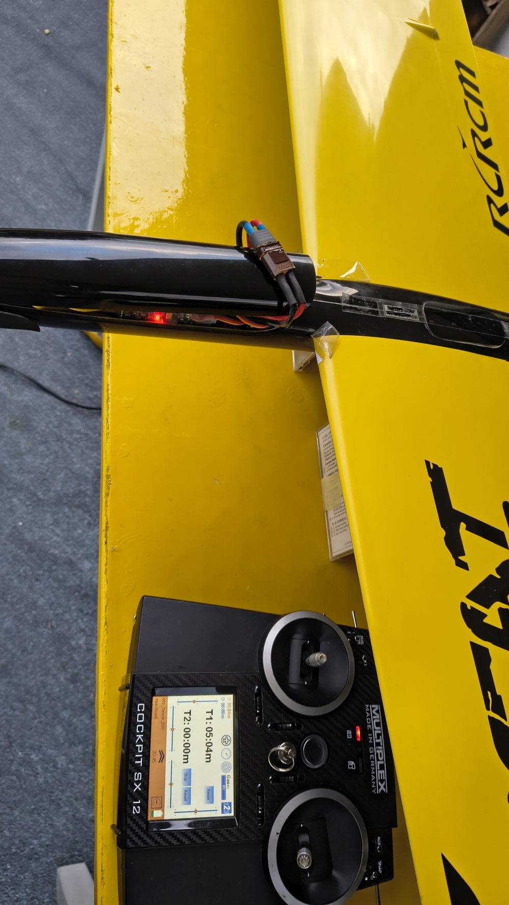
Anyway: it's incredibly tight with the servos—absolutely crazy on this model. Here's my recommendation, contrary to what the manufacturer says:
Just buy the right-side servos one size smaller. Then you won't have any headaches!
One lingering issue: the prop started on its own a couple of times—that's not how I want to fly. Still needs investigating.
I rearranged a lot of the cables, and then it fired up and shut right back down again. Still need to check if that's still a problem once everything is firmly wired.
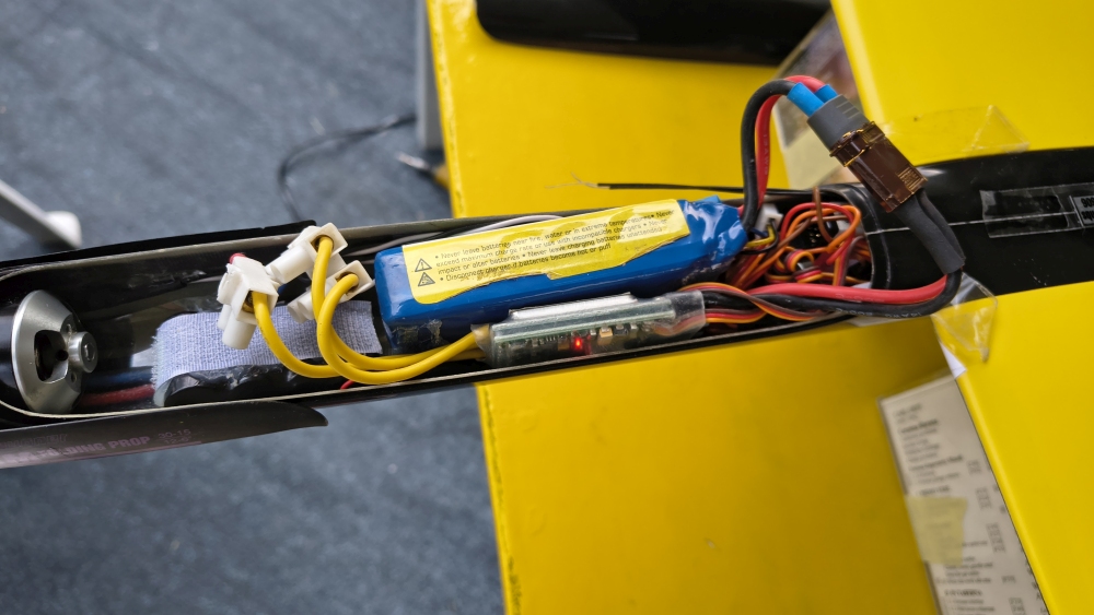
HOORAY! I WARM WELCOME THE TOMCAT
to my hangar. It will replace the Mystique 2.9.
Last preparations the day before
here you can see the power cables
- BEC cable battery 1
- Backup battery 2
- Regulator LiPo battery 2200 mAh
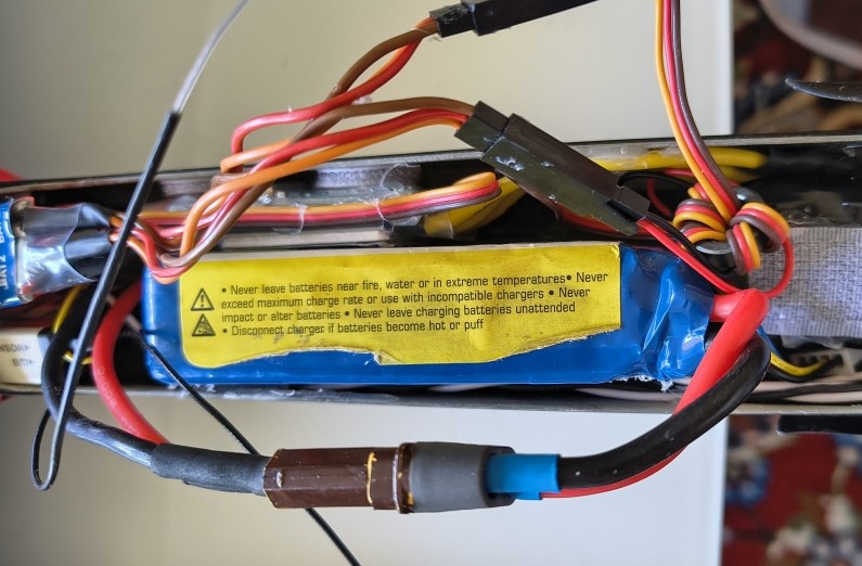
after all of this has been completed successfully
- A complete check of the functions and the motor
- A continuous test of the functions and the motor and the temperature = max 60 °C
- A range test with reduced range: Multiplex Cockpit SX—then you should have about max. 50 m
- Sensors: battery 1, battery 2
- Sensors: motor temperature and fuselage temperature
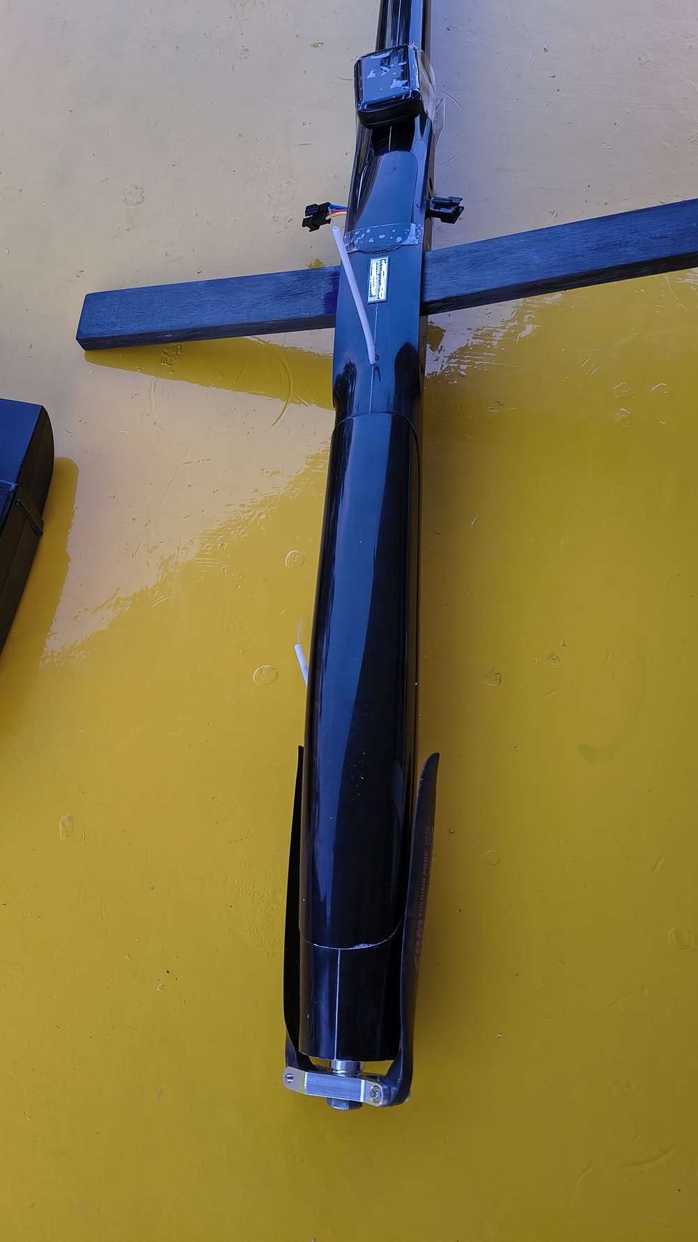
First flight 4.7.2026
with the model everything was built and set up very well; the first throw was then perfectly straight, completely balanced—everything was perfect
then the second throw with the motor started—the motor power was something like with Mystique 2.9; Tomcat inherited most of the parts from that.
so nothing unexpected to be expected
the first landing was okay
Then I re-trimmed the transmitter based on the findings from the first flight: elevator servo new neutral point, and also the ailerons.
Mixing amount for flaps and spoilers was too low for depth-rudder compensation.
I made a mistake. I then increased the mixing proportion from the flaps to the elevator.
unfortunately far too much—max was nonsense. On the next landing I then dared to do it:
set full flaps; as instructed, the model crashed into the ground from 1.5 m.
I could pull as much as I wanted. The accident was programmed by the mixer.
So the second landing became a “skid landing”.
The fuselage is cracked. Attached is a photo of how I applied two new layers of fiberglass:
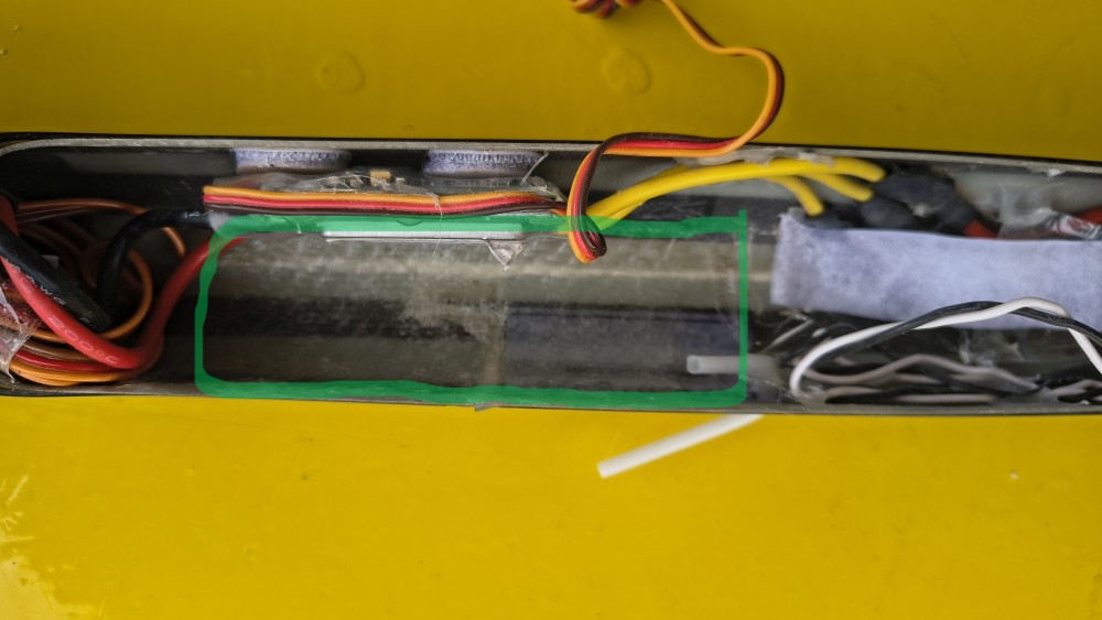
to make everything stable again. The motor was disassembled and cleaned—everything OK.
I removed the too-aggressive mixer settings again.
The model flies well and immediately took to thermals; I circled in lift for about two minutes.
It really doesn’t fly badly at all.
That’s it—with an almost successful first flight. Well, the first takeoff was perfect, just not the second landing—that’s the end of the build supervision. I hope I gave you a few helpful tips.